Design for Additive Manufacturing, Part 3
Here are the most common pitfalls when designing parts for additive manufacturing.
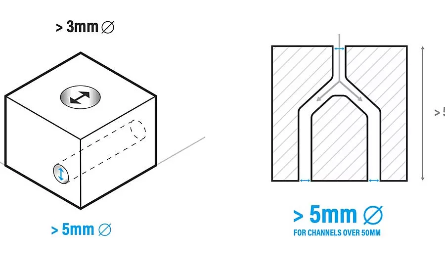
Powder can fuse into holes and channels with small diameters. To prevent this, we recommend a minimum diameter of 3 millimeters. Photo courtesy 3DPRINTUK
Different additive manufacturing processes have different constraints that can determine how easily and consistently they can produce parts. Photo courtesy 3DPRINTUK
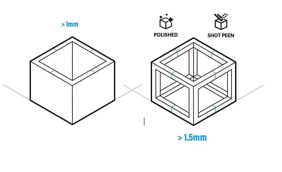
Our guaranteed minimum wall thickness for unfinished parts is 1 millimeter. For parts that will be polished or shot-peened, our guaranteed minimum thickness is 1.5 millimeters. Photo courtesy 3DPRINTUK
Different additive manufacturing (AM) processes have different constraints that can determine how easily and consistently they can produce parts. Some constraints are universal across the different processes; some are more specific to the type of process used. At 3DPRINTUK, we specialize in powder bed fusion (PBF) processes with polymer materials.
It is essential to understand the technology you are working with to maximize its potential as a production method. With this understanding, it is possible to design around the general limitations of AM, as well as the specific constraints of your particular process. Designing for AM requires a different approach than designing for traditional manufacturing methods.
While we are strong advocates of AM and what it can achieve, the key to our success during the past decade has been our understanding of the process’s limitations and how we manage expectations.
To that end, here are the most common pitfalls when designing parts for AM and, in particular, the selective laser sintering and multi-jet fusion processes.
WALL THICKNESS
Wall thickness is a critical consideration for parts being designed for AM, both in terms of the part itself and any post-processing that may be required. Our maximum recommended wall thickness will prevent shrinkage deformation during cooling, while our minimum recommended wall thickness will ensure parts withstand automated post-processing techniques without damage.
Our guaranteed minimum wall thickness for unfinished parts is 1 millimeter, but there are exceptions when this thickness should be increased. Exceptions include vulnerable unsupported structures, skeletal structures, weight-bearing walls, and specific performance requirements.
For parts that will be polished or shot-peened, our guaranteed minimum thickness is 1.5 millimeters. Again, there are exceptions for vulnerable unsupported features, weight-bearing walls and performance requirements.
Looking for quick answers on assembly and manufacturing topics? Try Ask ASM, our new smart AI search tool. Ask ASM
Our recommended maximum wall thickness is 5 millimeters. Anything beyond 10 millimeters may require the wall of the part to be hollowed out to prevent shrinkage deformation, build failures and excessive print times.
In most cases, a 3-millimeter wall thickness provides a rigid part with a little or no flex, while a 1.5-millimeter wall thickness results in some flex, depending on length and structural support.
SURFACE DETAILS
The nature of PBF processes mean that parts come off the printer with a granular surface. Sometimes, layer lines can be visible. Post-processing options, such as polishing or shot-peening, are often required to achieve a smoother finish more akin to injection molded parts. If specific surface details are designed into a product or part, certain design rules should be followed.
Surface details can vary depending on which surface they have been applied to. The top side may include a raised burr of the laser around the outer edge, while the underside can appear more muted. For the best and most consistent visibility, design text or features to appear on the side surfaces.
Other recommendations are as follows:
- Features should be a minimum of 0.5 millimeter wide and 0.5 millimeter deep.
- Embossed text is safer than raised text, since small details and edges can be vulnerable to break.
- Avoid embossing or extruding surface details too far. Try to keep them to around 0.5 millimeter. Anything further out can be damaged during post-processing. Anything too deep can trap powder.
SOLID VS. HOLLOW PARTS
Hollowing can prevent the part from deforming and achieve higher levels of accuracy and reliability. However, PBF processes work with powdered material, and hollow parts can trap powder within the sintered shell. When designing a hollowed part, there are a few design options that avoid trapped powder, such as designing-in escape holes, removing unwanted surfaces altogether, or including a locating lid.
We will automatically hollow larger parts before printing when they are above 15 to 20 millimeters on a case-by-case basis. If you want us to print it solid, let us know and we can advise accordingly.
INTERLOCKING AND MECHANICAL PARTS
When designing interlocking or mechanical parts, including a clearance between parts is essential. This is because a gap between the sintered surfaces prevents them from fusing together. The tighter the tolerance, the more likely it is to fuse together.
Some general design rules are as follows:
- In nearly all cases, a clearance between moving parts must be at least 0.5 millimeter for us to guarantee a result.
- Contacting surfaces must be kept to 5 millimeters or less to guarantee them not fusing. Longer shafts will likely be too difficult or impossible to free up.
- Think about how the trapped powder between the surfaces can be removed. Sometimes a little force is enough to remove the powder, but designing powder removal holes may also be needed.
- Dense volumes can refract more heat and harden the powder between the surfaces. This means that the clearance may have to be increased if this is flagged as a concern or if the part does not function as intended.
HOLES AND CHANNELS
One of the key advantages of AM is the ability to design and produce complex geometries without the need for expensive tooling. However, designers still have to be mindful of the complexities they design-in to parts, especially when it comes to holes and channels running through the part. The nature of PBF processes comes into play here—specifically the amount of heat that parts are exposed to during the build process. Thus, powder can fuse into holes and channels with small diameters. To prevent this, we recommend to design them greater than 3 millimeters.
For internal channels over 50 millimeters long, the same problem applies. It can be difficult to remove all of the powder. We recommend a diameter greater than 5 millimeters for internal channels. The same rule applies to curved holes, too.
MAXIMUM BUILD SIZE
3DPRINTUK will always position parts in a build to get the best possible outcome —no matter the original orientation of the file. The only exception to this is if a client locks the orientation while placing the order.
For more information, visit www.3dprint-uk.co.uk.
This might seem like an obvious one, but all additive manufacturing equipment—whether desktop, mid-range or full production systems—have a maximum build size. You would be amazed how often this can be overlooked!
Across our fleet of industrial-scale 3D printers, our maximum build sizes are:
SLS, PA12, 300 by 300 by 600 millimeters.
MJF, PA12, 350 by 255 by 350 millimeters.
SLS, flexible TPU, 180 by 120 by 120 millimeters
Editor’s note: This is the last of a three-part series about design for AM. Parts 1 and 2 explored the advantages additive manufacturing over traditional manufacturing processes, and the pitfalls to avoid to achieve the most successful outcomes.
Looking for a reprint of this article?
From high-res PDFs to custom plaques, order your copy today!


