Design for Additive Manufacturing
Several factors should be considered at the design stage to effectively produce parts using additive manufacturing methods.
In injection molding, a draft in the outer surface of a boss facilitates easy removal of the parts from the core and cavity of the mold. In additive manufacturing, such drafts serve as stiffeners. Photo courtesy Geometric Ltd.
For additive manufacturing, sharp corners in the XY plane should be filleted or chamfered to reduce stresses and to accommodate the natural radius inherent to the process. Photo courtesy Geometric Ltd.
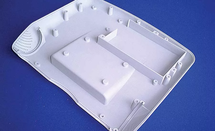
Selective laser sintering produced this plastic part. The minimum feature size that can be rendered by the technology is constrained by the diameter of the laser spot. Photo courtesy IMIRP Rapid Prototyping Ltd.
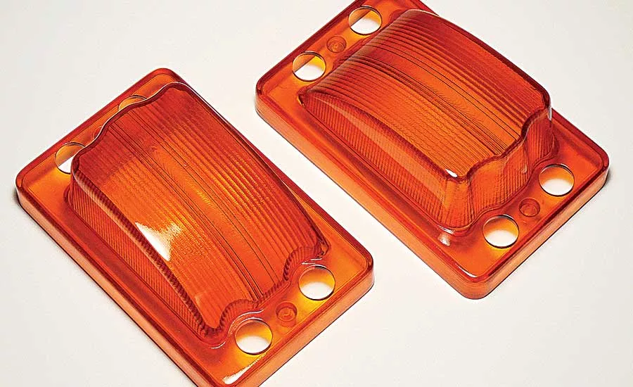
These translucent parts were made with stereolithography. Features such as overhangs and undercuts require support when created using this method. Photo courtesy Additive Manufacturing LLC
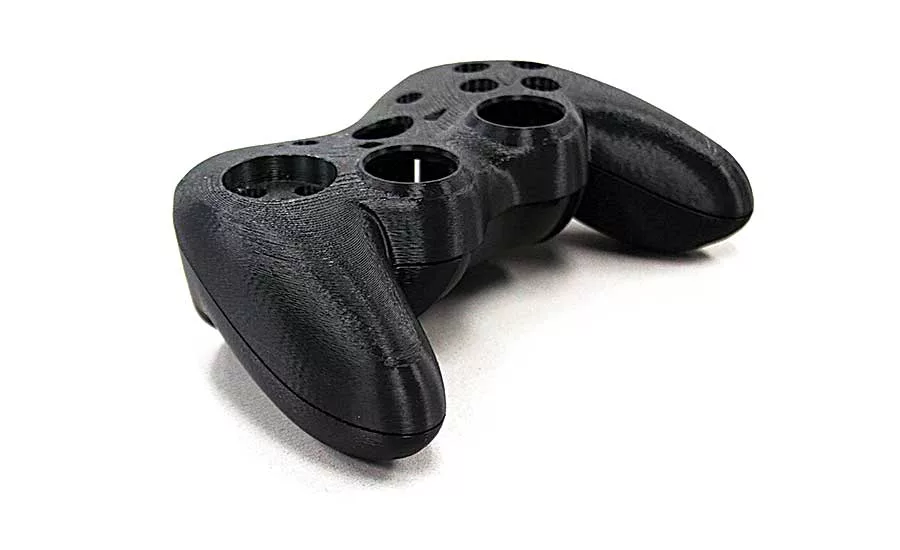
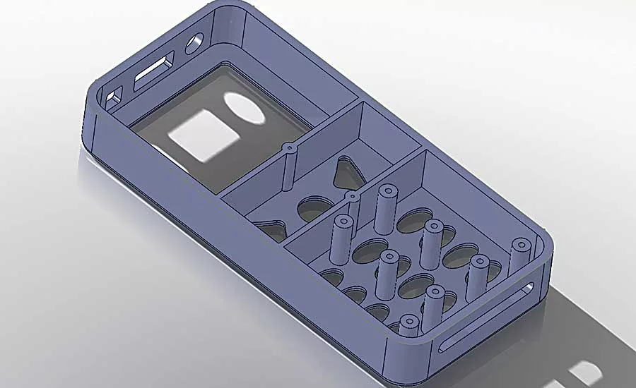
This prototype game controller was created using fused deposition modeling. Photo courtesy Forge Labs
Additive manufacturing has become a buzzword in manufacturing today. It has improved tremendously over the past few decades, and it is evolving from a technology for simple prototyping to one that can be used to make actual parts and tooling. The technology is already being used in myriad industries, including automotive, consumer goods, medical devices, aerospace and defense.
A variety of additive manufacturing methods have emerged: fused deposition modeling (FDM), stereolithography (SLA), PolyJet 3D resin printing (3DP), selective laser sintering (SLS), and direct metal laser sintering (DMLS). All these methods make parts by building up materials layer by layer.
In principle, any component can be made by either subtractive or additive manufacturing techniques. However, various design features pose completely different challenges to both methods. As the number of parts being made directly by additive manufacturing grows, it’s important to lay down design principles suitable for such processes and to ensure parts are designed for additive manufacturing. Several factors should be considered at the design stage to effectively produce parts using these technologies.
Maximum Part Size
The maximum size of additively manufactured parts is constrained by the size of the available machinery. If the part is bigger than the maximum capacity of the machine, the following methods can be adopted to solve the problem.
If the end use is only to create a prototype, then the part can be scaled such that the maximum dimensions fit the machine. Of course, due to scaling, some finer details could be lost depending on the scaling factor and the feature dimensions. This could require some editing or clean up in the scaled 3D model.
Alternatively, the part can be redesigned to fit the machine if the mismatch is small in dimension, or the part can be redesigned as a multipiece assembly. In the latter case, the model could be spilt into two or more pieces that can then be glued or welded together. This could also require some modifications or the addition of a few features to increase the joint strength.
Faces Requiring Support
Because additive manufacturing methods build the part layer by layer, some designs might require additional support during production. Features such as negative drafts, overhangs and undercuts require support in FDM, SLA and 3DP.
Looking for quick answers on assembly and manufacturing topics? Try Ask ASM, our new smart AI search tool. Ask ASM
As a consequence, such features should be avoided wherever possible. Creating part supports increases manufacturing time and that, in turn, increases cost. Parts requiring supports also might need secondary processes. The support might have to be cut away, and the joint lines might have to be sanded and cleaned.
Minimum Wall Thickness
The minimum wall thickness of a part depends on the additive manufacturing method and the resolution of the machine. Very thin walls could make the part fragile. As a result, engineers should maintain a minimum wall thickness to lend sufficient strength and rigidity to the part.
This is particularly true for faces requiring supports, such as negative drafts, overhangs and undercuts. The walls must be thick enough and strong enough to withstand the stress caused when support material is removed.
Another way to boost the rigidity of a part is by adding ribs. Added as protrusions from the walls, ribs can stiffen and strengthen the part enough that engineers can design walls to be thinner. However, tall ribs or long ribs can also create some problems. Ribs need to be designed in correct proportions of length, height and thickness to provide the required strength. Rib thickness should be large enough to be produced through additive manufacturing.
If ribs are too long or too tall, supporting ribs may be required. It’s better to use a number of smaller ribs instead of one large rib. For large surfaces, it is advisable to add rib networks. For additive manufacturing, it is recommended to increase the wall thickness rather than adding ribs to thin-walled structures. But, thick-walled structures increase the weight of the part and are more costly to produce. Engineers may need to make a tradeoff between design requirements and cost.
Boss Design
Part designs may have bosses, which serve as points for attachment and assembly. The most common boss designs consist of cylindrical projections with or without holes. Holes in bosses are designed to receive screws, threaded inserts or other fastening hardware. Under service conditions, bosses are often subjected to stresses not encountered in other sections of a component. So, bosses are generally designed with a draft to increase the strength at the bottom.
In injection molding, drafts in the outer surface of a boss also facilitate easy removal of the parts from the core and cavity of the mold. In additive manufacturing, such drafts serve as stiffeners. A fillet of a certain radius should also be provided at the base of boss to reduce stress. The radius at the base of the boss should be larger than a certain minimum value, depending on the additive manufacturing machine. Tall and slender bosses should be avoided. When designing bosses, correct proportions of height, outer radius, hole radius and hole depth should be observed to achieve the required strength.
Minimum Feature Size
The minimum feature size of various part features such as holes (blind or through), pockets (depression text, symbols or cutouts), islands (protruding text, symbols, bosses or pins) is constrained by the additive manufacturing method, machine resolution, wall thickness, and whether the feature is on a vertical or horizontal wall.
The minimum feature size is constrained by the bead width in FDM and the laser spot diameter in SLS. Machine manufacturers recommend that the minimum feature size along the X-Y plane should be greater than or equal to four times the resolution of the machine, while the minimum feature size along the Z axis should be greater than or equal to the machine’s resolution. To get more accurate parts from additive manufacturing, feature dimensions should be greater than these minimum sizes.
Also, all sharp corners in the XY section plane should be filleted or chamfered to reduce stresses and to accommodate the natural radius inherent to additive manufacturing processes. Fillet radii should be greater than the minimum natural radius, which is generally four times the machine’s resolution. Similarly, it will be impossible to produce knife edges with zero thickness at the edge, so it’s advisable to flatten such features to a minimum thickness.
Specific considerations should be taken into account when designing various features:
- Quality of holes depends on the wall thickness and the diameter of the hole. The minimum diameter that can be used increases with the wall thickness. In other words, the ratio of hole diameter to hole depth should be higher than a minimum specified value.
- The quality of pockets or cutouts depends on the wall thickness and the feature dimensions. The ratio of wall thickness to pocket depth should be higher than a minimum specified value. In addition, engineers should always maintain a minimum distance between features and between a feature and an edge.
- Text is similar to pockets and islands. Text should be larger than a minimum font size, and the manufacturing quality is generally better when they are placed in vertical walls than in horizontal walls.
- Bosses or pins should be larger than a minimum diameter, depending on the additive manufacturing machine.
Generally, 3D CAD models are converted to STL file format before manufacturing. STL files store the surface geometry of a 3D model by tessellating into triangulated surfaces, which introduces an approximation error for curved surfaces. Such errors are less prominent with finer tessellation. Thus, engineers should ensure that tessellation quality is set as per the allowable deviation, since it plays a major role in the quality of additively manufactured parts.
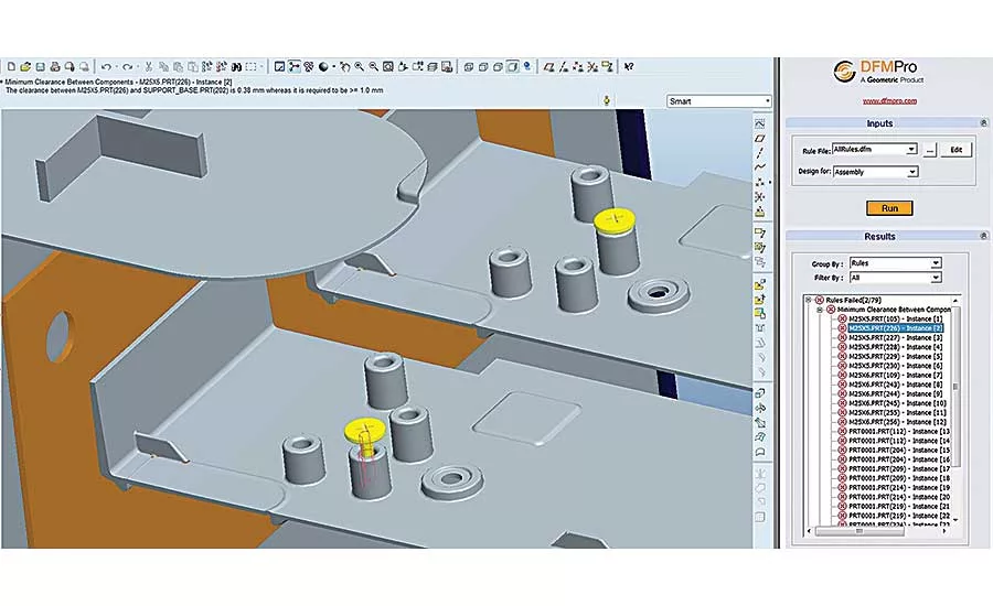
Geometric DFX
Although these design rules for additive manufacturing might appear simple, verifying all these rules manually in 3D models can be difficult and time-consuming. Manual verification can be prone to errors. There’s always the chance of missing a few checks. An automated system can help speed up the process and provide a standard way of verifying parts to avoid manufacturability issues.
Geometric DFX is design-for-manufacturing software that takes 3D parts as input and automatically analyzes all the manufacturability issues based on predefined rules. DFX highlights the rule failures directly in the 3D model and also generates xml and xl reports. The rules are configurable based on the machine and the type of additive manufacturing method. The software can handle a variety of CAD formats, including Pro/Engineer, NX, CATIA, SolidWorks, Inventor, STEP, IGES, Parasolid and ACIS.
By letting DFX check their models for additive manufacturing design rules, engineers can reduce multiple design
iterations and ensure that optimal designs are submitted for manufacturing. DFX helps lower manufacturing costs by decreasing design-to-manufacturing lead time and reducing the number of trial runs.
DFX software covers more than just additive manufacturing. The software includes modules with similar design-rule checks for other manufacturing processes, such as milling, turning, sheet metal processing, injection molding, casting and assembly.
13 Rules for Additive Manufacturing
When analyzing a design for additive manufacturing, DFX software checks the following:
- Maximum part size. Compares part size with maximum allowable part size and shows a failure if the part is larger.
- Minimum wall thickness. Compares wall thickness of the part and highlights regions where thickness is less than the minimum allowable thickness. This rule also helps to check for minimum distance between holes, cutouts or pockets and minimum distance from edges to pockets.
- Faces requiring support. Recognizes negative drafts, overhangs, undercuts and other features requiring support and highlights those faces.
- Minimum thickness of faces requiring support. Compares the thickness of faces requiring support against the minimum allowable thickness and highlights the faces that fail.
- Minimum feature size. Compares the sizes of pockets, islands, text and other features against minimum allowable feature size and highlights the features that fail.
- Recommended rib parameters. Recognizes ribs and compares the ratios of rib-base thickness to nominal wall thickness and rib height to nominal wall thickness against maximum allowable ratios.
- Rib reinforcement check. Compares the ratios of rib area to nominal wall thickness and rib width to nominal wall thickness against maximum allowable ratio and highlights the features that fail.
- Boss ID to OD ratio. Recognizes bosses and compares the ratio of their inner diameters to outer diameters against the minimum allowable ratio and highlights the features that fail.
- Boss height to OD ratio. Compares the ratio of boss height to outer diameter against the maximum allowable ratio and highlights the features that fail.
- Minimum hole diameter to thickness or depth ratio. Recognizes holes and compares their diameter-to-thickness (depth) ratio against the minimum allowable ratio and highlights the features that fail.
- Knife edge. Recognizes knife edges and highlights them.
- Recommended corner radius. Recognizes fillets and compares their diameters against the minimum allowable radius and highlights the features that fail. Also recognizes sharp edges and highlights them.
- XYZ slice dimensions. Checks whether all X-Y dimensions are multiples of four times the machine resolution and whether Z dimensions are multiples of the resolution and highlights the regions that fail.
To stay competitive in this era of globalization, it’s important to apply any means of reducing manufacturing lead time, cost and time to market. We all know that changes are less costly to implement early in the design process rather than later. Concurrent engineering can help, but additive manufacturing is such a new and rapidly evolving field that companies may not have the expertise to thoroughly and adequately review proposed designs.
By implementing Geometric DFX software, organizations can save time and money and produce first-time-right designs for additive manufacturing.
Looking for a reprint of this article?
From high-res PDFs to custom plaques, order your copy today!


