Wire Processing: Processing Coax
Special equipment is needed to cut, strip and crimp coaxial cable.
Anyone with a television is familiar with coaxial cable. However, this multiconductor cable is used in many more applications than connecting your television to a cable box.
In vehicles, coax connects antennas to mobile phones, radios and satellite receivers. In electric vehicles, it’s used as a power cable. In military and aerospace equipment, coax is used for radio and microwave transmission, data transmission, and instrumentation and control applications. Coax can be found in cell phone towers, recording studios and medical devices. There’s even a small piece of micro coax in every Nintendo Wii.
Because of its unique design, special equipment is needed to cut, strimp and crimp coaxial cable. Coax consists of two conductors separated by a dielectric material and wrapped by an outer jacket. The center conductor and the outer conductor form concentric cylinders with a common axis. (A variant of coax, triaxial cable, consists of three concentric conductors.)
The center conductor is typically solid or seven-stranded wire. This conductor can be copper, tinned or silver-plated copper, copper-clad steel, and copper-clad aluminum.
The dielectric can be polyethylene (PE), polypropylene, fluorinated ethylene polypropylene (FEP), polytetrafluoroethylene (PTFE), or expanded PTFE. The latter, made by Gore-Tex, is specified for its softness and flexibility.
The outer conductor, or shield, can be aluminum foil, a braided mesh of copper or aluminum, or a combination of the two. In corrugated coax, the outer conductor is made from a corrugated copper tube.
The outer jacket protects the cable from the environment. It can be made of polyvinyl chloride, PE, FEP or polyvinylidene fluoride.
Coax comes in a wide range of sizes. Jacket diameters range from 0.07 to 1.7 inches. The center conductor of micro coax can be as thin as 0.012 inch in diameter.
Because of its multilayer design, stripping coax is tricky. “You want to strip down to the center conductor without nicking it,” explains Pete Doyon, vice president of product management at Schleuniger Inc. “You want a nice, clean, flush cut on the face of the dielectric. You don’t want any particles, which can change the [cable’s transmission] characteristics at higher frequencies.
“You also want to cut the shield without damaging the dielectric. That’s tough, because as you’re cutting through the braid or foil, you’re using the dielectric as an anvil. If the dielectric is soft, like Gore-Tex, there’s nothing backing up the strands you’re trying to cut.
“You want to leave as light a nick on the dielectric as possible. It’s almost impossible not to leave a tiny mark, but some applications have strict requirements about that. For example, you’re not allowed to nick the dielectric in coax for hybrid vehicles. So [the stripping machine] will cut through maybe 80 percent of the shield, and the rest has to be done by hand.”
Ordinary wire is stripped with one or two V-shaped blades that move up and down, perpendicular to the wire. Coax is stripped with two to four straight, angled or curved blades that rotate around the wire, descending as they turn. The cable is held in place using two or more centering jaws that are concentrically aligned with the blades.
Rotary blades are typically good for 50,000 to 100,000 cables. Because rotary blades have a more generic shape than V-shaped blades, assemblers will not necessarily have to change blades to process cables of different thicknesses. However, depending on the machine, they may have to change the guide bushing to match the diameter of the cable.
Both fully and semiautomatic models are available for stripping coax. A benchtop semiautomatic machine looks like a large, electric pencil sharpener. The operator feeds one end of a cut cable into the bushing at the front of the machine. When the cable reaches the correct depth, the machine clamps it in place and the stripping blades go to work.
The machine can perform full, partial or multistage strips on any layer of the cable. Strip length and incision depth are programmable.
Depending on the operator, the cable and the number of processing steps, cycle time with a semiautomatic machine can be as little as 4 to 7 seconds per piece, or 450 to 600 pieces per hour.
The fully automatic machine looks like any other in-line machine for cutting and stripping wire, except that it includes a rotary cutter through which the cable can pass. Like other in-line machines, it can be paired with equipment for prefeeding, marking and coiling.
When stripping coax, the key to success often lies with the cable itself. “The biggest problem is the quality of the cable, because the equipment [can only reference the diameter of] the outer jacket,” says Doyon. “The machine assumes that the inner layers are concentric, but that’s not always the case. If you look at cheap cable from overseas, the thickness of the outer jacket can vary quite a bit, and that will affect the stripping of the underlying layers.”
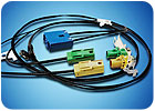
Today, thanks to the increasing use of coax in the automotive industry, one-piece, plastic-bodied connectors are now available from a number of suppliers. Called FAKRA connectors, these parts can be supplied daisy-chained on reels, just like metal terminals for conventional wire. And though a special applicator is needed, the connectors can be installed in one processing step with the same presses used for conventional wire.
FAKRA connectors require different process monitoring protocols than conventional wires. Because the machine performs two to three crimps simultaneously, pull force testing and crimp force monitoring are not the reliable indicators of quality they are with conventional wires.
“If the crimp force is way off, that can give you an indication of [a gross defect.] But otherwise, you don’t know what you’re looking at,” admits Doyon. “The force might be high in one zone and low in another, but the net could be OK.”
Instead, the best indicator of quality with FAKRA connectors is to periodically measure the height and width of each crimp.
Anyone with a television is familiar with coaxial cable. However, this multiconductor cable is used in many more applications than connecting your television to a cable box.
In vehicles, coax connects antennas to mobile phones, radios and satellite receivers. In electric vehicles, it’s used as a power cable. In military and aerospace equipment, coax is used for radio and microwave transmission, data transmission, and instrumentation and control applications. Coax can be found in cell phone towers, recording studios and medical devices. There’s even a small piece of micro coax in every Nintendo Wii.
Because of its unique design, special equipment is needed to cut, strimp and crimp coaxial cable. Coax consists of two conductors separated by a dielectric material and wrapped by an outer jacket. The center conductor and the outer conductor form concentric cylinders with a common axis. (A variant of coax, triaxial cable, consists of three concentric conductors.)
The center conductor is typically solid or seven-stranded wire. This conductor can be copper, tinned or silver-plated copper, copper-clad steel, and copper-clad aluminum.
The dielectric can be polyethylene (PE), polypropylene, fluorinated ethylene polypropylene (FEP), polytetrafluoroethylene (PTFE), or expanded PTFE. The latter, made by Gore-Tex, is specified for its softness and flexibility.
The outer conductor, or shield, can be aluminum foil, a braided mesh of copper or aluminum, or a combination of the two. In corrugated coax, the outer conductor is made from a corrugated copper tube.
The outer jacket protects the cable from the environment. It can be made of polyvinyl chloride, PE, FEP or polyvinylidene fluoride.
Coax comes in a wide range of sizes. Jacket diameters range from 0.07 to 1.7 inches. The center conductor of micro coax can be as thin as 0.012 inch in diameter.
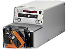
This machine strips semirigid coaxial cable up to 4.5 millimeters in diameter. It can also process conformable coax and Succoform noninsulated coax. Photo courtesy Schleuniger Inc.
Cutting and Stripping
Depending on the application, stripping coax may require two or three steps. In the two-step process, the jacket and the shield are removed to expose the dielectric. Then, the dielectric itself is cut to expose the center conductor. In the three-step process, the jacket is removed to expose the shield; the shield is cut to expose the dielectric; and the dielectric is removed to expose the conductor. (A triaxial cable may require a four- or five-step process.)Because of its multilayer design, stripping coax is tricky. “You want to strip down to the center conductor without nicking it,” explains Pete Doyon, vice president of product management at Schleuniger Inc. “You want a nice, clean, flush cut on the face of the dielectric. You don’t want any particles, which can change the [cable’s transmission] characteristics at higher frequencies.
“You also want to cut the shield without damaging the dielectric. That’s tough, because as you’re cutting through the braid or foil, you’re using the dielectric as an anvil. If the dielectric is soft, like Gore-Tex, there’s nothing backing up the strands you’re trying to cut.
“You want to leave as light a nick on the dielectric as possible. It’s almost impossible not to leave a tiny mark, but some applications have strict requirements about that. For example, you’re not allowed to nick the dielectric in coax for hybrid vehicles. So [the stripping machine] will cut through maybe 80 percent of the shield, and the rest has to be done by hand.”
Ordinary wire is stripped with one or two V-shaped blades that move up and down, perpendicular to the wire. Coax is stripped with two to four straight, angled or curved blades that rotate around the wire, descending as they turn. The cable is held in place using two or more centering jaws that are concentrically aligned with the blades.
Rotary blades are typically good for 50,000 to 100,000 cables. Because rotary blades have a more generic shape than V-shaped blades, assemblers will not necessarily have to change blades to process cables of different thicknesses. However, depending on the machine, they may have to change the guide bushing to match the diameter of the cable.
Both fully and semiautomatic models are available for stripping coax. A benchtop semiautomatic machine looks like a large, electric pencil sharpener. The operator feeds one end of a cut cable into the bushing at the front of the machine. When the cable reaches the correct depth, the machine clamps it in place and the stripping blades go to work.
The machine can perform full, partial or multistage strips on any layer of the cable. Strip length and incision depth are programmable.
Depending on the operator, the cable and the number of processing steps, cycle time with a semiautomatic machine can be as little as 4 to 7 seconds per piece, or 450 to 600 pieces per hour.
The fully automatic machine looks like any other in-line machine for cutting and stripping wire, except that it includes a rotary cutter through which the cable can pass. Like other in-line machines, it can be paired with equipment for prefeeding, marking and coiling.
When stripping coax, the key to success often lies with the cable itself. “The biggest problem is the quality of the cable, because the equipment [can only reference the diameter of] the outer jacket,” says Doyon. “The machine assumes that the inner layers are concentric, but that’s not always the case. If you look at cheap cable from overseas, the thickness of the outer jacket can vary quite a bit, and that will affect the stripping of the underlying layers.”
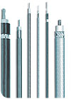
Stripping machines can perform full, partial or multistage strips on any layer of a coaxial cable. Strip length and incision depth are programmable. Photo courtesy Schleuniger Inc.
Crimping Coax
Until recently, connectors for coaxial cable were only available as loose parts. For example, a video connector consisted of a body, a ring ferrule and, perhaps, a contact for the center conductor. The number of pieces made automating the crimping process difficult, since each part had to be attached separately.Today, thanks to the increasing use of coax in the automotive industry, one-piece, plastic-bodied connectors are now available from a number of suppliers. Called FAKRA connectors, these parts can be supplied daisy-chained on reels, just like metal terminals for conventional wire. And though a special applicator is needed, the connectors can be installed in one processing step with the same presses used for conventional wire.
FAKRA connectors require different process monitoring protocols than conventional wires. Because the machine performs two to three crimps simultaneously, pull force testing and crimp force monitoring are not the reliable indicators of quality they are with conventional wires.
“If the crimp force is way off, that can give you an indication of [a gross defect.] But otherwise, you don’t know what you’re looking at,” admits Doyon. “The force might be high in one zone and low in another, but the net could be OK.”
Instead, the best indicator of quality with FAKRA connectors is to periodically measure the height and width of each crimp.
Looking for a reprint of this article?
From high-res PDFs to custom plaques, order your copy today!


