Maintaining Image Brightness in Vision Systems
A closed-loop approach is the best way to overcome variations in image brightness.
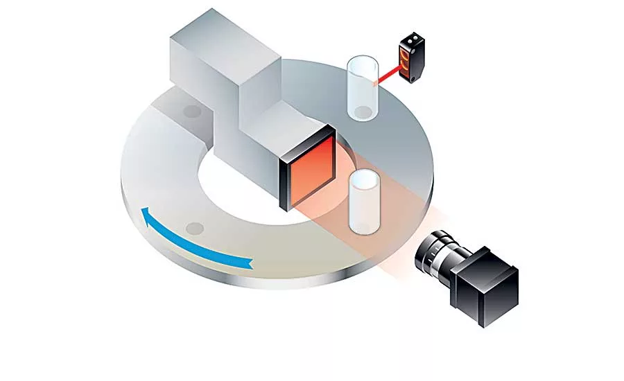
The quality and repeatability of vision inspection applications depends on consistent light intensity. Illustration courtesy Gardasoft LLC
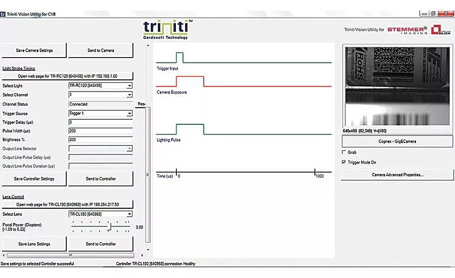
When using pulsed lighting, it’s essential to get the timing of the pulse and the camera exposure perfectly aligned to optimize image brightness. The Vision Utility interface provides a diagram that shows the timing of the camera exposure and the lighting pulse on one screen, so it’s easy to see when the two are not aligned. In the example shown here, the camera exposure is starting before the light pulse, so the image is quite dark. By adjusting the lighting pulse delay, the two can be easily brought into alignment. This updated configuration can be sent to the controller, and the image will be seen to be immediately brighter. When the user is happy with the timing values, they can be saved readily as the default configuration of the camera and controller. Illustration courtesy Gardasoft LLC
An intelligent lighting controller can automatically adjust the current to an LED to compensate for fluctuations in brightness related to operating temperature. Illustration courtesy Gardasoft LLC
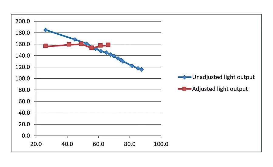
As LEDs heat up, their brightness drops by up to 40 percent. Gardasoft’s Triniti technology solves this problem. The chip built into a Triniti light allows the lighting controller to know the temperature of the LED and compensate accordingly. This graph shows how well this works. The blue line is the unadjusted light output, and the red line is the light output with the Triniti chip adjustment register. The X axis is the temperature in Celsius. The Y axis is the brightness, in milliwatts, measured by the vision sensor. As the temperature of the LED rises from 25 to 90 C, its light output drops by 37 percent. However, when compensation is applied, the variation is just 4 percent. Source: Gardasoft LLC
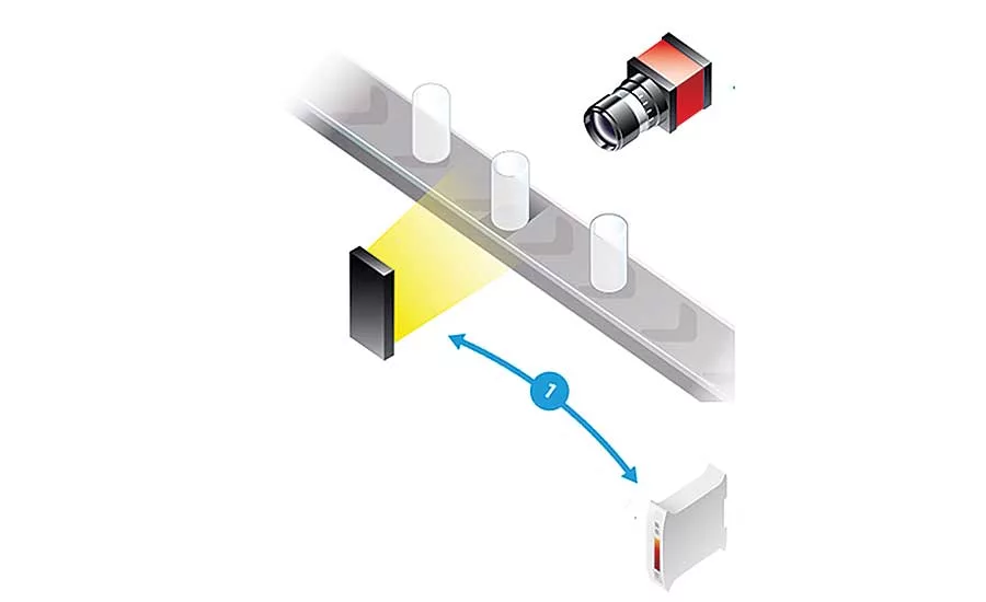
The best way to control image quality is to use a closed-loop approach based on the brightness detected by the camera itself. This is the most effective solution, since it accounts for any change in illumination conditions whether they result from the LED or an external condition. Illustration courtesy Gardasoft LLC
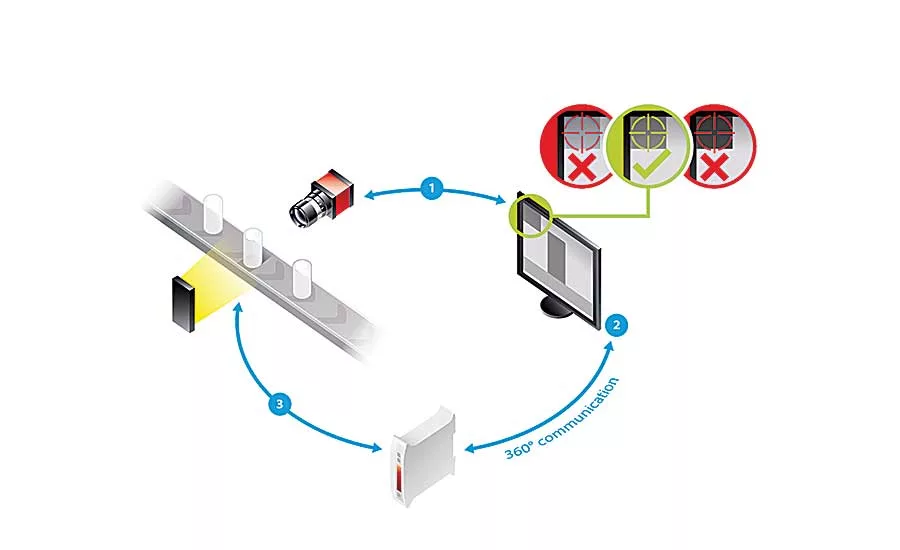
A closed-loop system is ideal for controlling image quality in machine vision applications. In addition to its designated function, the camera also measures a defined area of the scene for illumination intensity. (This area is effectively a “test card” for the camera.) Measurements of the test card are continuously reported to the image processing software, which compares the data to a predetermined acceptable bandwidth of illumination for the application. If the bandwidth is contravened, a signal is sent to the controller to increase the lighting intensity. Illustration courtesy Gardasoft LLC
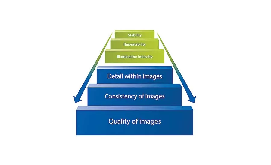
Vision systems are used to make critical measurements of parts and assemblies as part of a quality control system. Such measurements might be taken to determine the fitness of a component to progress to the next step in the manufacturing process, or they might be done at the end of the line prior to shipping the final product. Either way, it is essential that the measurements are both accurate and repeatable. Any variable, either internal or external, that affects the performance of the imaging system could affect the resulting measurements. This could lead to unnecessary line stoppages, excessive waste or even defective product reaching the customer.
Since measurements are made on the image of the object rather than the object itself, it’s important to optimize every element of the imaging process to achieve the best image possible. One of those elements is lighting. Illumination is hugely important to generate an image good enough for processing and measurement.
LEDs are the most commonly used illumination in machine vision applications. The type, orientation and wavelength of the light can all play a crucial role in delivering good images. However, stability and repeatability are absolutely essential for a vision system to perform consistently. Variation in illumination is unacceptable.
Image brightness is a function of the amount of light arriving at the image sensor. Clearly, the illumination source plays a critical role in this, but other components of the optical system—as well as external factors—also influence how much light gets to the sensor.
Any imaging system that has thresholding; that is looking for subtle features, such as surface defects; or that is performing color inspection will benefit from improving the repeatability of the light levels. Consistent illumination allows threshold parameters to be set closer to the background level. This enables detection of finer features and increases the contrast between target features and the background. Applications involving dimensional checking or the detection of gross defects, such as the presence of features, are more tolerant to variations in illumination intensity.
Lighting Control Methods
There are several control modes for LED lighting. Continuous operation is the simplest. The light is on all the time, and the light intensity is proportional to the current supplied to the LED by the controller. The maximum light intensity achievable is 100 percent of the LED manufacturer’s rating.
Pulsed lighting control is a popular alternative to continuous lighting and offers a number of significant benefits. In pulsed mode, the lighting is switched on only when required. The controller receives a trigger signal when a pulse is required. The delay from the trigger to the output pulse, the length of the pulse, and the intensity of the pulse are all configurable. Pulsing makes it possible to freeze the image of moving objects, making it ideal for high-speed imaging applications.
Looking for quick answers on assembly and manufacturing topics? Try Ask ASM, our new smart AI search tool. Ask ASM
Gardasoft’s controllers offer fine adjustment of the pulse timing, which is often more flexible than the camera’s timing. The camera can be set for a longer exposure time, and the light pulsed on for a short time to freeze the motion.
An additional benefit of pulsed operation is that it is possible to obtain more than 100 percent brightness from an LED by driving it with more current (up to 10 times its normal rating) for short pulses. This is known as overdriving. Gardasoft controllers are equipped with safety technology that allows overdriving to be carried out without risk of damaging the LED.
The intelligent lighting approach takes lighting control to a new level by networking the lighting, camera and imaging software to provide an integrated application with a single graphical interface for setup and control. Our Triniti intelligent lighting platform consists of three elements:
- Light identification and operational data. Special chips mounted into LED lights provide information on model data, electrical characteristics, optical characteristics and usage information.
- Integration of lights into software. These specially enabled LED lights can be seamlessly integrated into machine vision networks via a software development kit or an application program interface in major image processing packages. This provides engineers with a single graphical interface to set up the camera and lighting, visualize the timing and captured images, and save the settings to the camera and controller.
- Expert light control. The system incorporates all the functionality of LED controller technology.
This link between imaging software, cameras, lights and controllers means that the illumination level within the system is known at any time.
Factors Affecting Light Intensity
Controlling the light output from the LED is fundamental for maintaining constant image brightness. A number of factors affect light output, including age, temperature and the environment.
Although LEDs are remarkably reliable, their light output does deteriorate over time. This is due to minute “threading” dislocations in the LED crystal structure, which act as nucleation points for larger dislocations. Threading dislocations arise during the LED wafer manufacturing process. Larger dislocations form naturally as result of heating and cooling and consequent expansion and shrinkage during use as the LED is turned on and off. As the number of these dislocations increases over time, the quantum efficiency of photon production drops and light output decreases. The rate of decrease of light intensity is therefore a function of how the LED is driven for a given application and is difficult to predict. Typically, an LED would be replaced when its output falls below 70 percent of its initial rating.
As LEDs heat up from 25 to 90 C, their brightness drops by up to 40 percent. This is a huge variation that may not be seen during system commissioning, but which can cause variability during normal operation. A system turned on in the morning might start cold and have a higher level of rejects until the lights reach the temperature at which the system was commissioned. Variation in light output due to temperature is around 0.6 percent per degree Celsius. This can be significant, even over small temperature ranges.
LED light output is proportional to the current through the device, not the voltage, so all LED manufacturers specify that current control is advised for efficient use. Constant-current lighting controllers provide reasonable linearity in the brightness output, though the curve drops towards higher overdriving percentages.
Using the characteristic profile of output vs. current (provided by the light manufacturer) can enable linear brightness control, even for high levels of overdriving. Accurate regulation of the current is essential, since a 1 percent variation in current can lead to 1 percent variation in light intensity.
It is possible for the environment of the vision system to affect LED output. Dust, dirt, liquids or vapors may stick to the LED, reducing its light output. Another factor to consider is condensation when the LED is cold. This may affect light output due more to the cooling of the LED than absorption of the light by the condensation.
Other Factors
While accurate regulation of light intensity is critical for maintaining image brightness, a number of other factors can affect the amount of light reaching the image sensor.
Most machine vision systems try to exclude ambient light from the camera view to remove this as a variable. However, in some cases this is not possible—for example, if people are working in the same areas as a machine or a robot has a large work envelope that can’t be fully screened. By reducing exposure time, the effect of ambient light can be reduced. Of course, the lighting will typically need to be proportionally brighter, possibly by overdriving the LED. Keeping exposure time the same, but increasing the lighting brightness, allows the iris to be narrowed, which will also reduce the effect of ambient light.
Sometimes, it is possible to separate the two types of light. For example, if visible light is needed for the normal working environment, it may be possible for the vision system to use near-infrared light. Using narrow range visible lighting, such as LEDs or filtered conventional lighting, prevents visible light from affecting the image.
When using pulsed lighting, it is essential to get the timing of the lighting pulse and the camera exposure perfectly aligned to optimize image brightness. If they are not in alignment, the image will appear dark or, in the worst case, no image will be seen at all. By adjusting the lighting pulse delay, the two can be easily brought into alignment.
The Triniti intelligent lighting system enables engineers to set up the timing for the entire vision system, with cameras and strobe-mode lighting, all from one place. The Vision Utility interface provides a diagram that shows the timing of the camera exposure and the lighting pulse on one screen. It’s easy to see when the two are not aligned, and a live camera image shows the effect of the settings.
Some lenses do not provide repeatable F-stops. That is, different lenses set at the same F-stop may let in different amounts of light. This won’t produce variation from day to day, but it will cause variation from one system and another, which may be a problem for systems operating on multiple assembly lines. Engineers can compensate for this variation by using the gain control on the camera or by automatic adjustment of the iris. Gardasoft offers drivers for different types of automatic irises, so software control can be used to provide intelligent adjustments.
Dust, dirt, liquids or vapors can stick to the lens, as well as the LED. This can reduce light throughput and adversely affect image brightness. In these cases, compensation may be achieved either by increasing the camera gain or adjusting the image with the vision software. The latter can include adjusting thresholds and other parameters based on the operator’s judgement. However, if an image is not at the ideal brightness, the image processing software could produce a final image with less dynamic range. It is usually better to maintain the brightness of the original camera image, rather than compensate for lack of brightness during image processing.
Controlling Light Intensity
A major step in controlling image brightness is to optimize and maintain the LED output intensity.
As LEDs heat up, their brightness drops by up to 40 percent. Gardasoft’s Triniti technology solves this problem. A chip built into a Triniti light allows the lighting controller to know the temperature of the LED. The chip can also hold a temperature compensation profile that describes how light intensity changes with temperature.
Temperature and age compensation for lighting are predictive techniques. They will often provide significant improvements for no extra cost or system complexity. Image processing can check that the predictions are not wildly inaccurate.
Full closed-loop compensation will take away the work needed to generate and test such predictions. Closed-loop control based on an optical sensor can be used to maintain constant light intensity. An optical sensor is arranged to measure the brightness of the light and provide this measurement to the lighting controller. The controller has a target brightness and adjusts the current to the LED to achieve it.
Closed-loop systems are generally quite difficult to develop. It is only when all the components are in place and working that the closed loop can be tested. While under development, the compensation will frustratingly drift to its minimum or maximum setting if one of the components in the system is still in a prototype stage and hasn’t been completed yet.
Intelligent Lighting
The most comprehensive way to control image brightness is to use a closed-loop approach based on image brightness detected by the camera itself. This is the most effective solution, since it accounts for any change in illumination conditions whether as a result of the LED or any external condition.
The closed loop includes the camera, LED, lens and lighting controller. This does require certain features within the view of the camera, and it will require some custom development by the system designer. The closed-loop system is structured as follows:
- The camera identifies optimum illumination intensity for application.
- The image processing application monitors acceptable operating illumination bandwidths.
- The controller automatically adjusts lighting intensity as necessary.
To see how this works, let’s consider an inspection application involving a GigE vision camera and a Triniti-enabled LED light. In addition to its designated function, the camera also measures a defined area of the scene for illumination intensity. (This area is effectively a “test card” for the camera.) Measurements of the test card are continuously reported to the image processing software, which compares the data to a predetermined acceptable bandwidth of illumination for the particular inspection. If the bandwidth is contravened, then a signal is sent to the controller to increase the lighting intensity. The controller will then increase the intensity until illumination levels are back within the acceptable bandwidth.
This approach will not only compensate for variations in LED output intensity, but also for any variations in ambient light. The vision lighting can be reduced in brightness as ambient light gets brighter. The system will adjust light intensity without risk of damaging the LED, because the controller knows the maximum intensity of the light. In addition, the controller can send a “preventive maintenance” warning signal to replace the LED before any safety limits are exceeded. You can see a demonstration of this at the following link: www.youtube.com/watch?v=BNL7VnrZXw8.
When considering variability in image brightness, it’s essential to think about the tolerance in brightness that is acceptable, either within an individual system or from system to system. Having decided what measures to take to achieve this tolerance, careful consideration should be given to what extra performance or reduced maintenance times could be achieved by taking additional measures to maintain constant image brightness.
For more information, call Gardasoft at 603-657-9026 or visit www.gardasoft.com.
Looking for a reprint of this article?
From high-res PDFs to custom plaques, order your copy today!


