IAM 2015
Trends in the Design and Manufacture of Round-Tube Plate-Fin Coils from Smaller Diameter Copper Tubes
Aggressive environmental legislation has motivated the design of ACR appliances that use low- or ultra-low GWP refrigerants and yet deliver high system efficiency. To achieve these design criteria, heat exchanger engineers have sought to increase the capacity of heat exchanger coils without increasing the materials usage and overall weight. In response, tube makers began supplying smaller-diameter copper tubes with a wider range of surface enhancements.
Concurrently, equipment manufacturers have redoubled their efforts to produce manufacturing equipment to handle high volumes of smaller diameter tubes; and the availability of small-diameter tube technology also stimulated the development of computer simulation tools to optimization of tube circuitry and fin geometries. Both of these developments were covered in a 2013 IAM white paper [1].
Advances continue to be made in tube fabrication, coil manufacture, and system design. Taken together, these three disciplines have contributed to an atmosphere of creativity, imagination and innovation in product design. This paper describes recent developments in materials, equipment, and design software. It serves as a guide for coil designers and system manufacturers who are looking to stay abreast of the latest developments. For more details, the reader is referred to the excellent technical literature in the field and is encouraged to contact tube suppliers, software developers, manufacturing equipment makers and coil manufacturers directly.
Low-GWP Refrigerants Are “In”
The HVAC&R industry arguably does not change rapidly but it does change in time, whether driven by competition, government intervention or a combination of both. One needs only look back at the ozone crisis of the past century and the successful response of industry to realize that change is not only possible but also inevitable.
Today, most of the refrigerants in use have near zero ozone depletion potential and attention has been turned to the global warming potential of refrigerants. This presents more challenges to the industry but solutions appear to be available.
Candidate refrigerants include Low Global Warming Potential (GWP) hydrofluorocarbons (HFCs) such as HFC-32, which has a GWP of 675; and ultra-low GWP hydrofluoroolefins (HFOs), such as HFO-1234yf and HFO-1234-ze, which have GWPs of 4 and 6, respectively. Scores of refrigerants that are blends of HFCs are HFOs are also under consideration for various applications. Such refrigerant blends can be tailored to the application by making tradeoffs between performance, cost, GWP and flammability.
Looking for quick answers on assembly and manufacturing topics? Try Ask ASM, our new smart AI search tool. Ask ASM
Tube Diameters Are Getting Smaller
Refrigerant and refrigerant tubes go “hand in glove.” For most refrigerants, there is no better fit than copper, its high thermal conductivity, superior strength and excellent corrosion resistance set it apart from any other material. Stainless steel and aluminum tubes exist but the vast majority of heat exchanger coils and refrigerant distribution lines are still made from copper.
The trend for the past ten years has been toward smaller diameter copper tubes, which are advantageous in many respects. Firstly, the internal heat transfer coefficients (HTCs) are higher for smaller diameter tubes, offering an immediate payback because less tube material and less refrigerant is required to provide the same capacity, whether for the evaporator or the condenser. Secondly, the smaller diameter tubes can allow for more efficient and more streamlined airflow outside of the tubes as can be easily shown with simulations. Thirdly, a given tube wall thickness can support higher pressures for smaller diameter tubes, which means tube walls can be made thinner, resulting in even less materials usage and even lighter weight.
On occasion, promoters of aluminum tubes point to “microchannel” or “multichannel” brazed aluminum, a technology borrowed from the auto industry, as offering better performance than copper. If one examines closely the details of such comparisons, it usually turns out that the multiple small channels in a flat tube are being compared to large diameter copper tubes, typically 3/8 inch tubes (9.52 mm tubes). The comparisons are misleading since smaller diameter copper tubes are the new benchmark for copper tubes. Exaggerated claims about aluminum microchannel tend to deflate when comparisons are made with MicroGroove smaller diameter copper tubes [4]. Further, the microchannel tubes present their own disadvantages, such as maldistribution of refrigerant, drainage and defrost obstructions, and other challenges. Meanwhile, MicroGroove coils just keep getting better.
As far as materials go it is hard to imagine a better material for heat transfer than copper. A few materials have better thermal conductivity, notably silver or diamond. Nonetheless, copper offers a unique combination of thermal conductivity and strength, which makes it likely that it will serve as the material of choice for tube material for the foreseeable future.
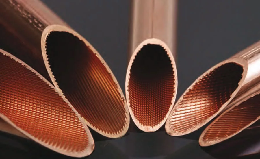
Perfecting the Inner Groove
Another trend is to provide surface enhancements to the inside surface of the copper tubes. Again, this increases the inside-the-tube heat transfer characteristics. Much research has been dedicated to understanding the behavior of various refrigerants as they flow through small, inner-grooved tubes at various rates. Here theory and manufacturing capability are closely intertwined. Generally speaking, a grooved inner surface mixes up the refrigerant for more efficient heat transfer between the refrigerant and the tube wall. Surface enhancements can improve the performance of copper tubes both in condenser coils and evaporator coils.
In the case of inner-grooves or microfins for tubes, the grooves have widths on the order of hundreds of microns at the top of the groove. It is remarkable that these inner grooves can enhance the HTCs by as much as 300 percent depending on the tube diameter, the flow rate, the refrigerant and the type of enhancement. The variability in HTC enhancement has spurred competition among tube suppliers, who are the experts in fabricating tubes with various kinds of enhancements, for example, herringbone or helical patterns.
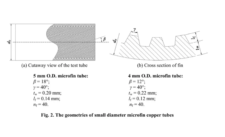
Tube manufacturers today can vary the features of the microfins in many ways. They can vary the width at the top of the groove. They can vary the depth of the groove. They can vary the groove wall angle, the helical angle and spacing between the grooves. Incidentally, the term “microgroove” is reminiscent of the record industry where the term was used to describe the narrow grooves of long playing records introduced in the late 1940s. These “microgrooves” were 50 microns (2 mils) or less at the top compared to earlier coarse grooves which were 150 microns (mils) or less at the top. [5,6] This term “microgroove” is therefore apropos for describing the inner surface enhancements of copper tubes, which are of a similar order of magnitude[7].
Nowadays, the number of tube enhancements has proliferated to such an extent that it is necessary to work closely with tube suppliers to optimize the configuration for any given application. The performance of these tubes must then be correlated with laboratory experiments for specific refrigerants, flow rates, pressures, and quality factors. Tube suppliers and/or research labs can provide the necessary correlations to allow for accurate predictions of the efficiency gains that can be realized by using inner-grooved smaller diameter tubes.
A recent white paper prepared by OTS and BOTI reviews the enhancements available for tubes of different tube diameters from 9.5 mm to 5 mm and smaller. [8] This joint research is on-going with OTS, BOTI and the Copper Alliance to correlate the surface enhancements with enhanced HTC values and lowered pressure drops. These values already have been precisely measured for commonly used surface enhancements and in many cases have been included in the industry-standard software for designing heat exchanger coils.
High-strength Copper Alloys
The refrigeration cycle is typically more demanding for eco-friendly refrigerants than for the refrigerants that are being phased out. In particular, the tubes, fittings and components must withstand high pressures.
One copper alloy that can be used in heat-exchangers is deoxidized, high phosphorus copper (also known as Cu-DHP). The phosphorus removes the oxygen but does not significantly affect thermal conductivity although it does affect the electrical conductivity [9]. The standard designation for this alloy is ASTM/USA CDA C12200. This alloy is useful up to 120 bar or more, depending on the tube diameter and tube wall thickness.
Plain and inner-grooved seamless tubes and fittings are available in a high-strength copper-iron alloy known as CuFe2P (and also known as C19400 or CW107C). The alloying elements are iron, zinc, phosphorus and magnesium. These alloys allow for a reduction of wall thickness and hence less material usage. What’s more, existing machines and tools usually can process these alloys, and they are perfectly brazeable and weldable. These alloy tubes can sustain pressures 100 percent higher than standard ACR tubes. Various sized tubes for refrigerant distribution typically are rated to handle pressures up to 120 bar (i.e., 1740 psi or 12 MPa).
The product literature of copper tube suppliers should be consulted for more information about high strength copper alloys.
Modern Manufacturing
MicroGroove technology has been steadily advancing on all fronts. The development of smaller-diameter copper tubes has been accompanied by a parallel development in the manufacturing technology for the production of MicroGroove heat exchanger coils.
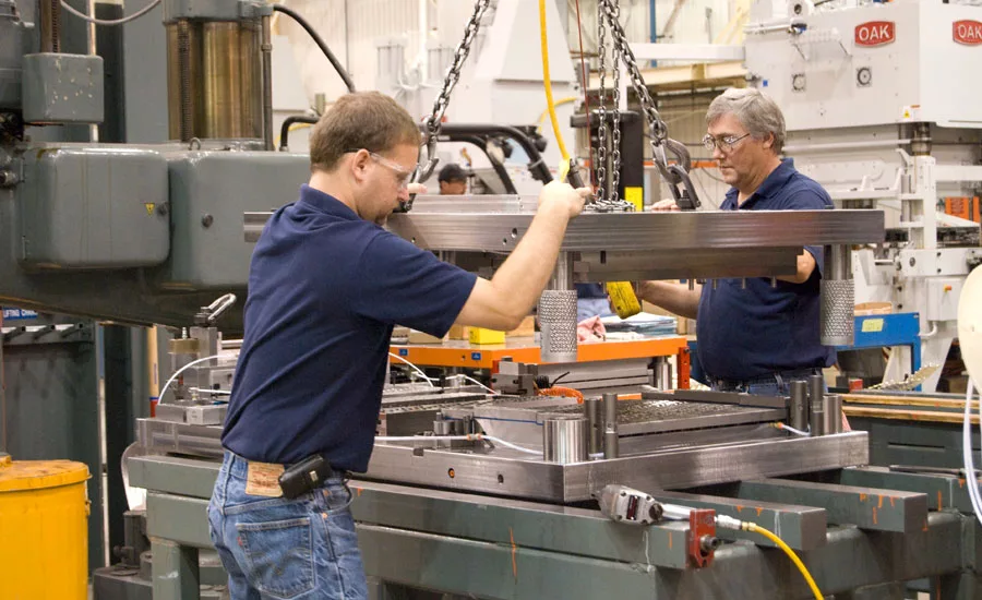
Today, the manufacturing infrastructure for supplying evaporators, condensers and gas coolers to the industry has developed to the point where it is readily available for use. In particular, specialized equipment has been developed to establish modern, highly automated production lines.
These production lines include:
- Presses and dies for stamping fins with patterns optimized for smaller diameter tubes;
- Hairpin benders capable of high-speed processing of smaller diameter tubes;
- Materials handling tools for lacing the delicate hairpins through the fin plates;
- Tube expanders for establishing thermal contact between the tubes and fins; and finally
- Various automated or semi-automated methods for the insertion and brazing of the return bends into the flared, open-ends of the copper tubes, completing the tube circuitry.
In some cases ACR OEMs have developed their own “in-house” equipment for various steps to give them a competitive edge with a captive supply of high-efficiency coils. Today, such equipment is widely available for purchase globally from equipment makers. Any company today could purchase turnkey systems for making its own smaller-diameter “round tube, plate fin” (RTPF) coils.
Each of the above steps is independent of the others, with the specialized equipment delivering an intermediate product to the next step in the production line. Each step has evolved and has been refined to a high degree. Fin stamping, for example, makes use of sophisticated fin dies that allow for closely-spaced hole-patterns and optimized collar heights. The presses may exert 160 tons of force in the stamping process to allow for high throughput while minimizing floor-space requirements. High tonnage presses allow for the use of thicker fins and fin materials with higher tensile strength. Fin design and subsequent tooling of fin dies is a key element in the competitive production of heat exchanger coils.
Additional advances in equipment include the development of various methods of tube expansion as described below.
Joining Tubes and Fins
The manufacturing process of RTPF coils creates a rigid assembly from parts that are individually rather delicate. As described earlier, small diameter tubes have much higher strength for resisting internal pressure. However, when not assembled into a coil, the small diameter of these tubes can make them weaker in resisting bending and buckling.
The joining of tubes and fins is what makes the assembly strong. For smaller diameter tubes, depending on the wall thickness, higher forces may be required to expand the tubes but tube expansion is still practical. In addition to creating a rigid assembly, the joint between the tube and fin creates a path for heat conduction. If the tubes are improperly joined to the fins then the boundaries between the tubes and fins can become barriers to heat flow.
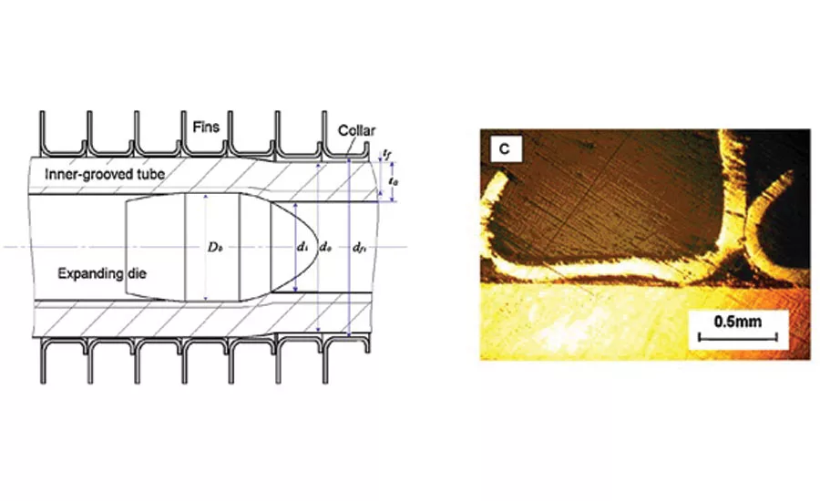
The preferred method for joining tubes and fins is through a process of tube expansion to generate an interference fit between the tube and the extruded fin collar. This expansion is typically performed using a spherical “bullet” that is pushed through the tube by a smaller diameter rod. The bullet diameter is larger than the original tube inside diameter, causing the tube to expand.
Friction between the tube and bullet induces column loading on the tube, which could cause the tube to buckle if not contained. Also, as the tube expands in diameter, material along the length of tube is drawn into the increased circumference of the tube; consequently the tube shrinks in length during the expansion process. Early adopters of small diameter tubes faced challenges in the expansion process, which led to development of “limited-shrink” expansion by OEMs. This approach enabled successful expansion by placing the tube in tension to prevent buckling and to control shrinkage. The proper balance of bullet friction force and tube tension also allows zero shrinkage of the tube.
Non-Invasive Tube Expansion Breakthrough
New technology being launched by Burr OAK Tool of Sturgis, Michigan, USA incorporates the proven technology of tube expansion to join the tube and fin. The new product, which is set to be released to the market in November, “uses precisely controlled pressure to expand tubes for an interference fit between the tubes and fins,” according to Jason Halling, Manager of Business Development & Marketing for OAK. The method of using pressure to expand tubes is commonly used in the hydroforming industry where containment for the final tube shape is determined with dies that encapsulate the material. In the case of expanding MicroGroove tubes into fins, the fin collar provides the necessary containment, resisting expansion and establishing a secure bond between the tube and fin. Halling explains that pressure expansion is not a new process to the HVAC industry. Some manufacturers routinely use pressurized fluids to expand coils. “This solution has inherent benefits that the industry will use to take MicroGroove to the next level,” states Halling.
Regarding non-invasive expansion, according to Roger Tetzloff, Innovations Manager for OAK, there are at least three benefits:
1. Zero Shrink Process
Tetzloff explains that pressure expansion is inherently a zero shrink process. Lévy-Mises equations describing plastic flow in material are used to show that a tube experiences zero lateral strain while pressure is applied to expand the tube diameter plastically [14]. In effect, the internal pressure that causes hoop stress in the tube resulting in expansion of the tube diameter also places tension on the tube, in the precise amount needed, to prevent the tube from shrinking. “This is really exciting,” explains Tetzloff, “when you understand the impact that compressive loading and bullet interaction can have on the tube and fin bond.” Tang, Li, and Peng of the School of Mechanical Engineering in Shanghai have studied the effect of collar compression[15]. Test results indicate improvements in the tube-to-fin contact of coils that are expanded with the non-invasive pressure approach rather than mechanical bullet expansion.
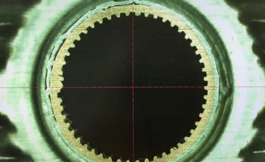
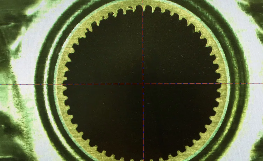
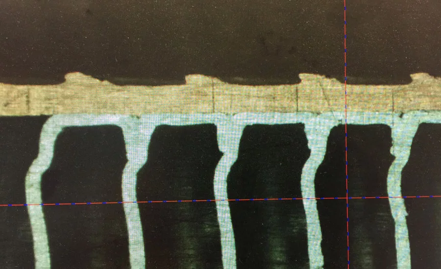
2. No Deformation of MicroGrooves
The second significant advantage of using pressure to expand tubes is that the internal tube enhancements are not disturbed as they are when using a mechanical bullet. This comparison is illustrated in images of small diameter internally enhanced MicroGroove tubes. For the bullet method, the stresses exerted in the internal enhancements of the tube are significant. The bullet method could deform the tops of fragile types of inner fins. Expanding tubes with pressure will enable tube manufacturers and researchers to explore new designs of surface enhancements.
It can be seen then that the use of a non-invasive expansion process opens the door to the use of more delicate inner-fin structures. The immediate effect is that existing enhancements will be unaffected by the manufacturing process. This phenomenon is already being tested in joint research by the ICA, OTS and BOTI, to determine what effects, if any, the method of expansion method has on the performance of surface enhancements and the values of heat transfer coefficients.
As mentioned above, microfins could increase refrigerant-side heat transfer coefficients as much as 300 percent, depending on the tube diameter. For a heat exchanger made with 5-mm MicroGroove tubes, the use of a microfinned tubes rather than a smooth tubes could increase the heat capacity by more than 20 percent; alternatively, it could reduce fin material mass and tube material mass up to 10 percent and up to 17 percent, respectively. Additional work is ongoing to further investigate MicroGroove behavior and potential. With new software methodology in place, the effects of enhancements can be explored to identify new geometries that increase heat transfer performance.
MicroGroove Design Software
In an ideal world, it would be possible to immediately simulate the effects of different tube sizes and surface enhancements on the HTCs and pressure drops, depending on the refrigerant flow rates and temperatures.
As a matter of fact, that scenario is already close to being realized. Laboratories are measuring how various inner surface enhancements correlate with the performance of the tubes that they supply. These real-world correlations can then be built into future editions of CoilDesigner® software[16].
To obtain the highest performance from ACR systems made with smaller diameter tubes, it is necessary to apply certain principles to the design of fin-and-tube heat exchangers, including design principles for tube-and-fin geometries and spacing, fin-configuration and tube circuitry. These step-by-step design principles are covered elsewhere
More recently, research at leading international universities has resulted in the development of new airside and refrigerant-side correlations, particularly for 5 mm MicroGroove tubes. To make such correlations readily available to HVAC&R system designers and heat exchanger engineers, the Copper Alliance is working with Optimized Thermal Systems Inc. to implement the newly developed correlations into CoilDesigner® software, a proprietary heat exchanger simulation and design optimization tool developed by the Center for Environmental Energy Engineering (CEEE) at the University of Maryland.
Conclusion
The manufacture of heat exchangers incorporating Microgroove technology primarily uses established and proven equipment to meet the ever increasing demands of higher efficiencies and environmental concerns. However, equipment manufacturers are continuously innovating as MicroGroove technology pushes the envelope of existing processes. As diameters continue to decrease, producers are finding new solutions to the manufacturing challenges faced with this exciting technology.
References
1. Nigel D. Cotton, Bob Weed and Wenson Zheng, “Building Better Appliances with Smaller Diameter Copper Tubes,” International Appliance Manufacturing, October 2013.
2. Yoram Shabtay and Nigel Cotton, “Heat Exchangers for Alternative Refrigerants,” RSES Journal, December 2014.
3. Yoram Shabtay, John Black, Frank Kraft, “New Copper-based Heat Exchangers for Alternative Refrigerants,” The International Refrigeration and Air Conditioning Conference. Paper Number 2570, Purdue University, 2014.
5. Wikipedia, entry on Gramophone record. https://en.wikipedia.org/wiki/Gramophone_record#The_microgroove_.26_vinyl_era
6. R.G. Gupta, “Audio & Video Systems,” Tata Mcgraw-Hill Education (2001).
7. Guoliang Ding et alia, “Two-phase heat transfer characteristics of R410A-oil mixture flow condensation inside small diameter microfin copper tubes” Conference on Thermal and Environmental Issues in Energy Systems, Sorrento, Italy, May 2010. The American Society of Mechanical Engineers (ASME), the Associazione Termotecnica Italiana (ATI), the Unione Italiana di Termofluidodinamica (UIT) and International Centre for Heat and Mass Transfer (ICHMT).
8. “A Review of the Influence of Microfin Enhancements on the Condensation Heat Transfer Coefficient for Small Diameter Tubes,” unpublished report from OTS and Burr Oak Tool Inc., 2015.
9. J.R. Davis, editor, “ASM Specialty Handbook: Copper and Copper Alloys,” 2001.
10. Examples of equipment makers with expertise in RTPF manufacturing equipment are Burr Oak Tool Inc. and Zhongshan OMS Industrial Company.
11. Newell Franks, “A New Era of Coil Manufacturing,” AHR Expo Technology Seminar, Dallas, 2013. Slideshow presentation available at www.microgroove.net/six-seminars-microgroove-technology-commercial-systems
12. MicroGroove Series of Webinars, “The Manufacture of ACR Coils with Smaller Diameter Copper Tubes” by John Hipchen, See www.microgroove.net/webinars . Also available on the MicroGrooveTech YouTube Channel.
13. MicroGroove Series of Webinars, “The Manufacture of High-Efficiency Coils with MicroGroove Copper Tubes” by Brian McConnell, President, Burr OAK Tool Inc. See www.microgroove.net/webinars . Also available on the MicroGrooveTech YouTube Channel.
14. Frank L. Kraft and Tommy L. Jamison, “Mechanical Behavior of Internally Pressurized Copper Tube for New HVACR Applications,” Journal of Pressure Vessel Technology, ASME, December 2012, Vol. 134 / 061213-1.
15. Ding Tang, Dayong Li, Yinghong Peng, “Optimization to the tube–fin contact status of the tube expansion process,” Journal of Materials Processing Technology, 211 (2011) 573–577.
16. CoilDesigner® software, a proprietary heat exchanger simulation and design optimization tool developed by the Center for Environmental Energy Engineering (CEEE) at the University of Maryland.
17. Wei Wu, Guoliang Ding et alia, “Principle of Designing Fin-and-Tube Heat Exchanger With Smaller Tube for Air Condition,” The International Refrigeration and Air Conditioning Conference. Paper Number 1217, Purdue University, 2012.
Looking for a reprint of this article?
From high-res PDFs to custom plaques, order your copy today!


