Joining: Failsafe Fusing
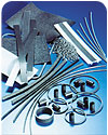
Emabond
electromagnetic materials can be provided in many different shapes and
configurations.
There are many critical plastic-part assembly applications where the long-term integrity of the joint is absolutely essential, such as when the assembly must contain a liquid. Examples include various small household appliances, oral hygiene appliances, or parts for major appliances, such as a dishwasher arm or clothes washer pump assembly.
Over the years, many manufacturers of such applications have achieved that desired assembly integrity by using the electromagnetic weld/bonding system developed by Emabond Solutions, Norwood, N.J., which offers a number of advantages over alternative methods such as adhesive bonding, heat staking, vibration, hotplate, or ultrasonic welding.
Recently, Emabond has developed a new line of RF generators with flexible power-delivery systems. These power-delivery systems utilize a faster, higher-precision RF technology that delivers enhanced product and process reliability in plastic assemblies designed for demanding environments.
The new RF power delivery system platform, along with other recent technical advancements, effectively eliminate or greatly reduce many of the perceived and real limitations of the Emabond process, thereby presenting many new application opportunities.
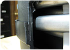
Cutaway
view of a tongue-and-groove joint in a high-pressure vessel whose top and
bottom glass-filled polypropylene pieces were joined using the Emabond
process. The proximity of internal
metal mass and delicate internal components (at right) made the assembly a
challenging design for which the Emabond process proved to be a good solution.
How it works
The Emabond process uses high-frequency induction energy coupled with conductive or electromagnetic materials to precisely deliver heat to a bond line to provide effective welding of virtually all thermoplastic materials.In the product development cycle, OEM design engineers work with Emabond engineers on the proper joint design for the process. Next, they work on designing the shape and thickness of the preform that will be placed into the joint. The preform contains the electromagnetic or conductive materials essential to the process. (See photo.)
The materials are custom formulated to meet the needs of each application’s performance requirements. The conductive fillers in the material must be compatible with the thermoplastics used in the parts to be joined. The type and quantity of conductive filler also influences energy absorption and, subsequently, the amount of heat that will be generated at the bond line. Sometimes, a simple, ferromagnetic filler such as iron will be appropriate. In other cases, recently developed ceramic fillers can be used to provide more exacting control of the temperature.
Applying the material as a die-cut preform, like a gasket, is one of the simplest methods from an assembly standpoint, but the material can be supplied in a variety of fashions, including extruded profiles, sheet, tape and ribbon. The material can also be co-extruded or co-injected directly onto the substrate of one of the mating parts. The Emabond engineers help OEM designers determine the optimal method for a specific application.
The photo above shows an image of a tall, shear, tongue-and-groove joint that joins two glass-filled polypropylene parts to form a tank that holds liquid under high pressure. The proximity of internal metal mass and delicate internal components made the assembly a challenging design for which the Emabond process proved to be a good solution.
The tongue and groove joint offers the greatest versatility, especially when leak proof and high-pressure results are required. However, joint designs can also be flat-to-flat, flat-to-groove and step.
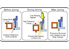
Fig.
1. Sequence illustrates how the Emabond process works.
Before joining: The preform is positioned in the joint. The mating parts are brought together and placed within a fixture containing a work coil that conforms to the weld line geometry. This phase is easily automated or operator initiated.
During joining: The activated coil heats the Emabond material, causing the adjoining plastic surfaces to melt. Energy is only consumed during the actual heating cycle, which typically is between 1 second to 30 seconds. Low clamping force is applied via the specially designed fixture to allow efficient transfer of melt temperature to the substrate.
After joining: The Emabond material has filled the gap and the process has fused the mating parts, resulting in a polymer-to-polymer, permanent weld. The joint’s cross-section is more compact than one joined by a frictional method of assembly that typically requires broader surface area and/or flash traps.
The Emabond process is a non-contact, non-violent method of assembly that is gentle on plastic parts. And it can join certain dissimilar materials, such as highly filled thermoplastics and flexible elastomers to rigid substrates. It also meets or exceeds demanding requirements such as NSF, for temperature-resistance, leak-proof and pressure-tight properties, and aesthetic appearance.
In addition to supplying the specialty joining materials, Emabond also supplies the equipment and control systems that manage the process.

Fig
2. Conceptual illustration showing how heat is produced at bond line.
Improvements
The new line of solid-state RF generators with flexible power-delivery systems has advanced the technology by providing welding process control and feedback. Historically, Emabond systems used tube-type generators that operated at variable frequency ranges from 2 MHz to 8 MHz and offered limited feedback capability. The new power-delivery system accurately controls the application of energy at the bond line, and the generators are FCC compliant and CE Approved. The RF generator is programmable, and the controller provides self-diagnostics and a multitude of process control capabilities on the welding process.The immediate advantages include:
- 1.
Precise control of energy at the bond line, including ramped power stages or
pulsing of power.
- 2. Minimal or no heating of non-plastic
components, such as metal and delicate electronics that may be near or captured
within the weld line at time of assembly.
- 3. Flexible, moving-power application packages
that can allow for spot welding and or continuous scanning of a bond line.
- 4. Wider overall power spectrum ranging from 1 kW
to 5 kW.
- 5. Lower overall system cost savings.
Static to dynamic
br> Previously, Emabond RF Power supply delivery was considered as a static process - similar in many ways to other forms of plastic welding such as ultrasonic, laser, hotplate and vibration. Parts were generally held stationary in a fixture while energy was applied either via friction or external thermal sources. The advent of the flexible power-delivery system has allowed parts to be moved while under pressure within a fixture while the RF energy is uniformly applied, making it now a dynamic process. Two options are possible: the power source can travel with the assembly, or the assembly can be moved past a fixed RF power source. This allows the non-contact, non-violent application of energy to a wider range of part geometries.
br>For example, a system was recently designed to perform multiple welds sequentially to assemble a high-pressure vessel. The part is transported under pressure during the assembly process to sequentially weld an upper and a lower end cap to create a high performance pressure tank. This system readily adapts to accommodate a wide range of tank sizes.
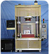
Solid-state Emabond tank welder adapts to different sized vessels.
Design flexibility
The Emabond Process is designed to meet a broad range of plastic assembly challenges from product design to the manufacturing floor. Successful projects using Emabond require optimization in three areas:- Application design for components, joint
design, and material selection.
- Emabond material formulation,
the material configuration, and assembly insertion
procedure.
- Equipment design and integration.
All three aspects must be working in harmony to provide optimal performance of the process.
The use of higher performance thermoplastics have created assembly application challenges that include:
- Assemblies with high structural loading,
often using materials with a high content of glass reinforcements.
- Vessels
with high internal pressures and long term cycling.
- Complex
assemblies having internal metal components or sensitive electronics.
- The need for continuous welding of sheets and films.
The pressure vessel joint photo exemplifies some of those points and demonstrates how recent advancements let designers solve a difficult combination of design challenges.
The Emabond RF generators with flexible power-delivery systems offer product manufacturers a highly efficient, compact, easy-to-integrate source of induction welding power for a wide variety of process applications. The highly reliable power supplies enhance process flexibility, deliver a wide operating power range for optimized process control, ensure high process repeatability, and improve throughput. The Emabond process should be considered by any manufacturer who must produce a high-value, failure-proof, plastic assembly, and by manufacturers whose assemblies contain delicate components contained within a plastic structure or vessel.
For more information, email: schookazian@emabond.com
Source: appliance DESIGN
Looking for a reprint of this article?
From high-res PDFs to custom plaques, order your copy today!


