Understanding and selecting the right process for plastic part assembly, Part II
Once you’ve had an opportunity to review plastic part assembly and joining options, you can finish out the selection process with some guidelines in mind.
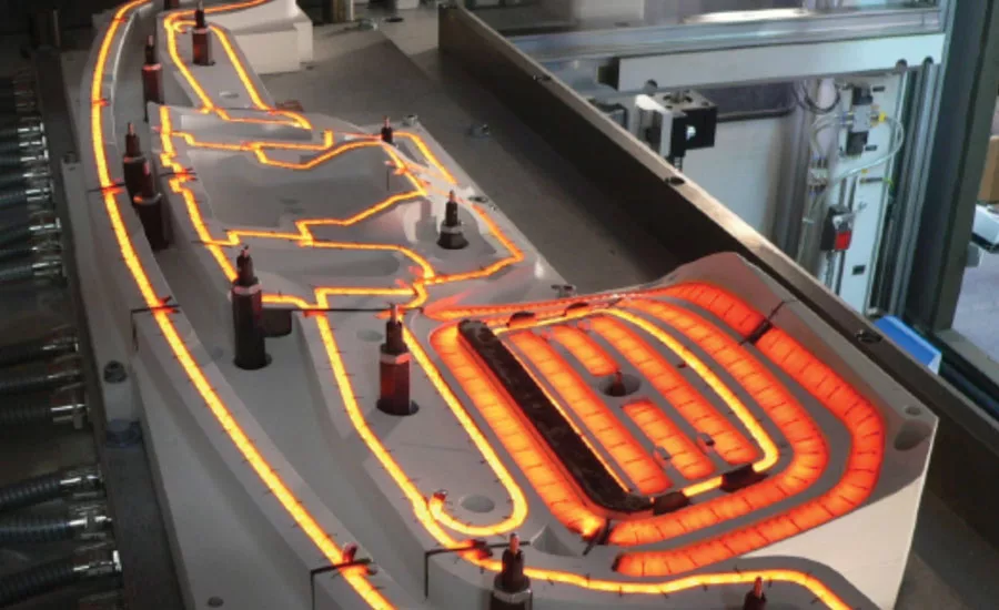
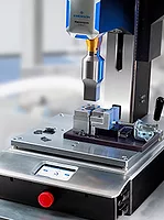
Figure 7: Infrared weld tooling featuring contoured infrared technology. Source: CIT Catalog
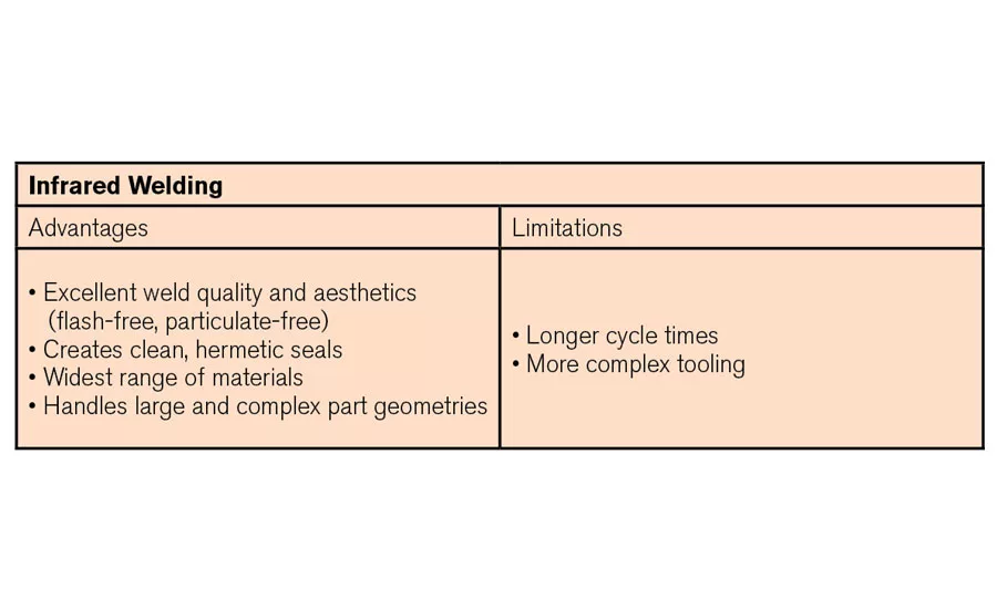
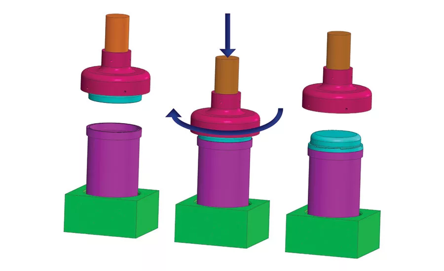
Figure 8: Spin welding process steps. Spin welds are achieved by rotating one part half against the second, stationary half while under a clamp load.
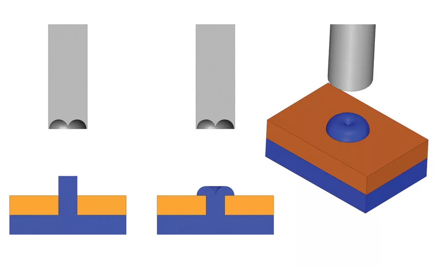
Figure 9: Thermal processing
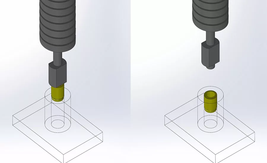
Figure 9: Thermal processing
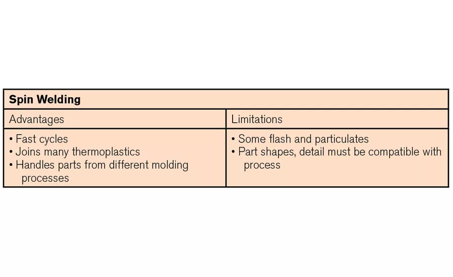
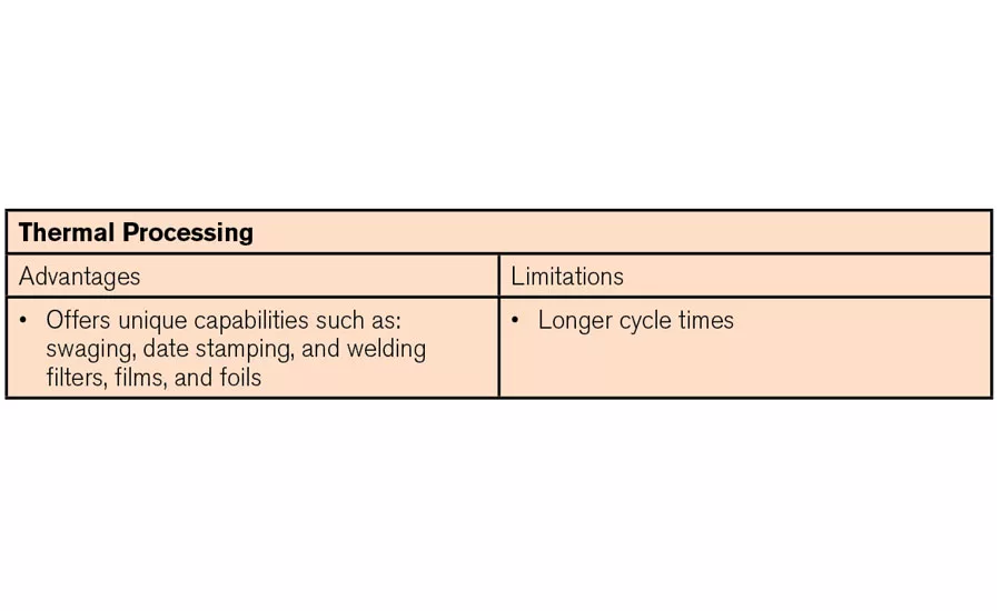
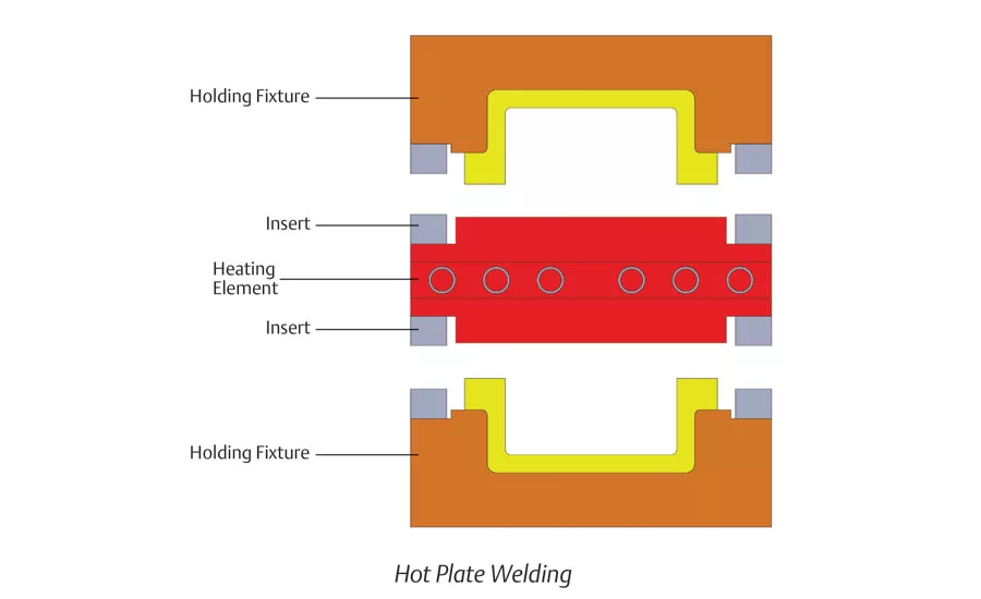
Figure 10: Hot plate welding process
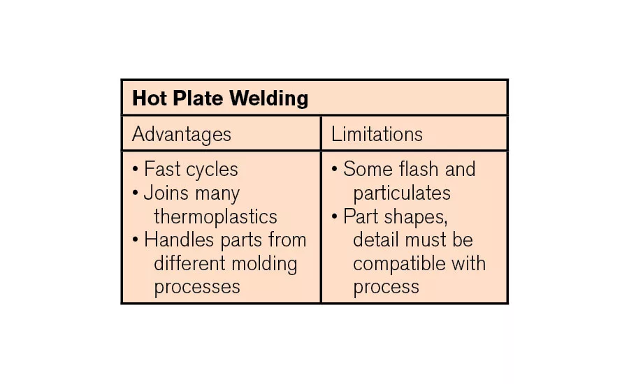
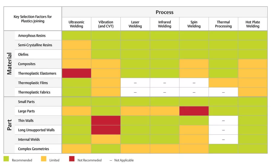
Figure 11: Key Selection Factors for Plastics Joining. Keep in mind that the chart represents our recommendations and likely results, based on experience. Often, there are exceptions: Items marked “limited” are often application or part dependent, so don’t rule out the possibility of getting excellent results.
Plastic welding isn’t one technology—the term encompasses a range of joining technologies that continue to evolve to meet a wide range of assembly needs. In rough order of their popularity and usage in the marketplace, plastic welding technologies include: ultrasonic welding, vibration welding, laser welding, infrared welding, spin welding, thermal processing, and hotplate welding.
In June’s part one, we discussed the first three technologies. Here we’ll discuss the remaining four: infrared, spin, thermal processing and hotplate welding.
Infrared Welding
Laser welding uses an infrared heat source—a laser light—to generate heat for welding. In terms of the spectrum of light, lasers generally straddle the edge between visual light and a wider, invisible category of light called infrared. Thus, the next category of plastic welding—infrared welding—shares a number of similarities with laser welding, while offering even greater versatility.
Infrared welding is a noncontact welding method that places contoured, metal-foil emitters between the mating surfaces of parts that are to be joined. These emitters deliver precise levels of invisible, radiant heat to mating surfaces for specified intervals, then are removed so that the heated, mating surfaces can be compressed and cooled in the weld tooling to produce a strong, airtight, and homogenous weld. Infrared welds are clean and virtually free of particulates and flash.
Because infrared emitters can be contoured over large and complex surfaces and surface features (joints, internal walls, sharp or curved edges), infrared welding can be used on parts that are too large for laser welding and too complicated for vibratory welding methods. Infrared is also very versatile when it comes to materials: It can join a broad spectrum of plastics, including high-temperature thermoplastics and semi-crystalline resins such as polyethylene and polypropylene.
Because of its ability to join even large, contoured parts with clean, precise welds, contoured infrared technology (CIT) has become more and more popular in many applications. Figure 7 shows infrared weld tooling that incorporates CIT. The tooling is used to heat large components, and then removed so that part halves can be welded under clamp pressure to form automotive dashboards or under-the-hood components like fluid reservoirs, air ducts, or housings.
Spin Welding
The spin welding process is, like ultrasonic and vibratory welding, a friction-based method of joining two thermoplastic parts. Spin welds are achieved by rotating one part half against the second, stationary half while under a clamp load. The spin creates the heat needed for the materials to melt. Once the rotation stops, the parts are held together for a small amount of time to solidify the bond. Naturally, the joint between the two components to be welded must be circular.
Looking for quick answers on assembly and manufacturing topics? Try Ask ASM, our new smart AI search tool. Ask ASM
System elements include a rack-mounted actuator that contains the motor for rotation and either a pneumatic cylinder or electric motor to supply the clamp pressure that completes the weld. The controller manages rotation speed, actuator motion and pressure, timing, and other parameters of the weld process.
There are many advantages of using spin welding over other welding techniques. High strength hermetic seals are achievable. Weld times are relatively short (one to two seconds) with total cycle times in the five to seven second range. The process is not as material specific as in ultrasonic welding with most thermoplastics being able to be processed. You can also weld materials from different molding processes (i.e. injection-molded to extruded or blow-molded parts) so long as melt flow index and melt temperatures of the mating parts are very similar. Spin welding also accommodates “far-field” welds—where the mating surfaces of the welds are relatively far (greater than ¼ inch) from the horn-contact surface—another plus relative to ultrasonic welding, for example. Orientation between the two parts is also possible with the use of a servo system.
The primary limitation to spin welding, depending on the materials being welded, is that it tends to create flash and particulate as a result of the joining process. And, although some joint designs (e.g. tongue-and-groove types) enable parts to capture weld flash, none are able to completely capture the particulates generated during spin welding. In addition, spin-welded parts must also incorporate a locating/drive feature in the parts so they can be properly positioned, then either driven or held by the tools so that no slippage can occur during the spin welding process.
Thermal Processing
Thermal processing is a plastics joining technique that utilizes a heated tip in direct contact with the plastic to soften and reform it into a desired shape, as seen in Figure 10, at top. When used to install inserts or other metal components, the tip contacts the metal part, transfers heat through it into the plastic, then drives the metal part into the plastic, as seen in Figure 10, at bottom. Thermal processing is most closely associated with staking and inserting components onto printed circuit boards, but can be used for a number of applications such as swaging, date stamping, and welding filters, films, and foils.
Thermal processing, as with all processes, has advantages and disadvantages compared to other plastic joining methods. In general, the range of suitable plastics is wider for thermal than for ultrasonic welding. The process is “gentle,” meaning that it can be performed without damaging fragile components, such as those common to circuit boards. Yet, components that are inserted or staked with this process have higher jack-out/torque-out values than ultrasonically installed inserts. The process is easy to scale up: multi-cavity tools can easily stake or insert large numbers of parts without increasing overall cycle times. The process is also quiet in operation and generally does not generate a lot of particulates.
The principal limitation of thermal processing is that it may require longer cycle times. The transfer of heat from the tip and through the plastic is the controlling factor. This factor often can be offset by machine/tooling design that allows for larger batches to be processed in each cycle.
Hot Plate Welding
The major advantage of hot plate welding is that virtually any shaped part can be welded, so long as a heat insert can be made to match the curvature of the part halves. Another advantage of hot plate is that the weld flash produced is solid and homogeneous. It will not break or flake off and particulate flash is not created. This is an advantage in markets such as medical and some business and consumer parts. Hot plate welding can also be used to “correctively” melt parts that are out of tolerance. The process accommodates large parts with complex shapes and can weld multiple parts in a single cycle.
Hot plate welding technology is straightforward: Parts are loaded into holding fixtures and brought into contact with a heat platen consisting of a heating element and two heat inserts. Once the mating surfaces are brought up to the melt temperature of the base resin, the heat platen is removed and the parts are brought together to form a weld. The tooling that touches the plastic parts (the heat inserts) are typically coated with Teflon as a release agent. Teflon is a wear item so the heat inserts have to be recoated on a regular basis as part of a PM schedule.
The limitations of hot plate welding include relatively long cycle times (30 to 50 seconds is typical) and relatively high energy consumption compared to other weld processes.
Selecting the process that is best for your application
Now that you’ve had an opportunity to review plastic part assembly and joining options, you can finish out the selection process with some guidelines in mind.
- Start with material. Part material can be a key limiting factor in joining process selection. For example, the effectiveness of ultrasonic welding may be limited when it is used with olefin materials, such as polypropylene or polyethylene, though all of the other processes generally join olefin parts very effectively. Similarly, ultrasonic welding is not recommended for joining thermoplastic elastomers and has limited applicability for joining composites.
- Then, consider part size, geometry, and structure. For smaller parts, any of the processes may do the job, provided the material is compatible with the process. But as part size increases, considerations change, based on limitations of tooling size, part shape, and part design and structure. Consider these examples:
- For ultrasonic welding, tooling size—and therefore part size—is a limiting factor. The lower the frequency used to ultrasonically weld (e.g., 15 kHz), the larger the tool required, up to a maximum of approximately 10” x 10.” The opposite is also true: higher frequency ultrasonic welding (e.g., 40 kHz) requires smaller tooling, up to a maximum part size of about 2.5” by 2.5.” If part sizes fall outside these ranges, processing will require either multiple ultrasonic welds or use of one of the other processes.
- Part geometry—the complexity of the part and its weld profile—can be a substantial limiting factor in process selection. Certain processes readily accommodate more complex geometries while others cannot. And, recent technology innovations, including clean vibration and contoured infrared, continue to expand the capability of proven processes to handle geometrically complex parts.
- Internal walls and wall thicknesses must also be considered. Vibration welding due to its linear reciprocating motion has difficulty welding long unsupported walls, while other technologies do not have an issue with these part features.
- Consider production volume and cycle speed. A number of processes, including ultrasonic, spin, and laser welding will process assemblies in seconds, while hot plate welding may take 40 to 50 seconds. So, among processes that will do the job, cycle speed counts. Note that in many cases, it is possible to adapt tooling to handle multiple parts in a single cycle to improve throughput.
- Lastly, evaluate capital equipment cost. Though it is sometimes difficult to do, making capital equipment cost the last consideration is the key to a sound assembly process selection.
If you narrow the field using the criteria above, your ultimate selection will be well suited not only to the assembly application, but to the efficiency and output of your entire production process. Go into the decision-making process with an open mind and a “process neutral” approach. By evaluating the advantages and limitations of each process available, and by working closely with equipment and solution providers, you are sure to identify and develop a solution that is ideal for your application.
Looking for a reprint of this article?
From high-res PDFs to custom plaques, order your copy today!