Understanding and selecting the right process for plastic part assembly
The key variables in assembly and joining operations continue to evolve rapidly.
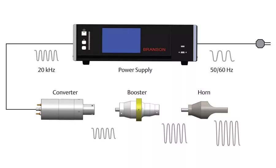
Figure 1: Conversion sequence for ultrasonic welding. This shows how the power supply, converter, booster and horn function together to create mechanical vibration.
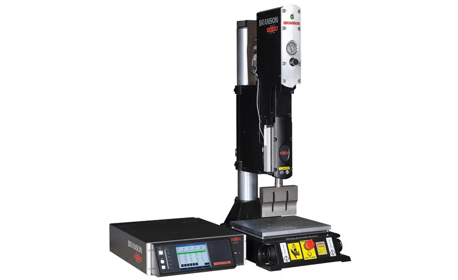
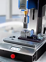
Figure 2 shows is a typical bench type ultrasonic welding system, the Branson Ultrasonics 2000X system. The actuator base and column can be removed which provides an excellent configuration for integrating into automation. The actuator is used to deliver the converter, booster and horn (commonly known as stack) to the parts being welded and applies force.
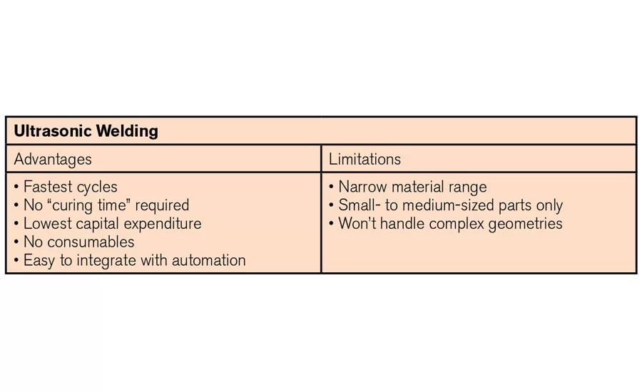
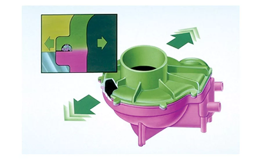
Figure 3: Part-to-part motion in the vibration welding process.
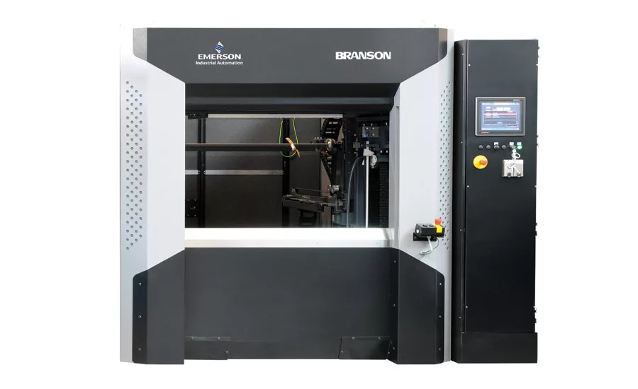
Figure 4: GVX Vibration Welder. This shows a large vibration welder, which can process parts up to 30 x 70 inches in size. Parts are loaded/unloaded through the front door. Controls linked to the power supply at right close the doors, manage the weld cycle, and reopen the doors, enabling removal of the completed part. Typical weld cycles range from five to 15 seconds, depending on part size
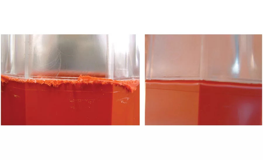
Figure 5: Comparing vibration and CVT welding. At left is a standard vibration welded polycarbonate to a polycarbonate/ABS part. At right is the same part welded with Clean Vibration Technology (CVT), which eliminates most weld-related flash.
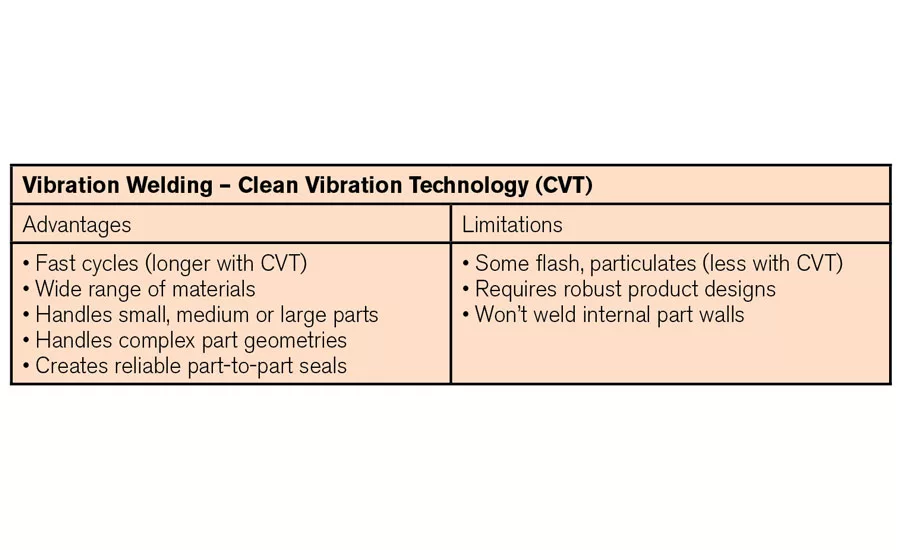
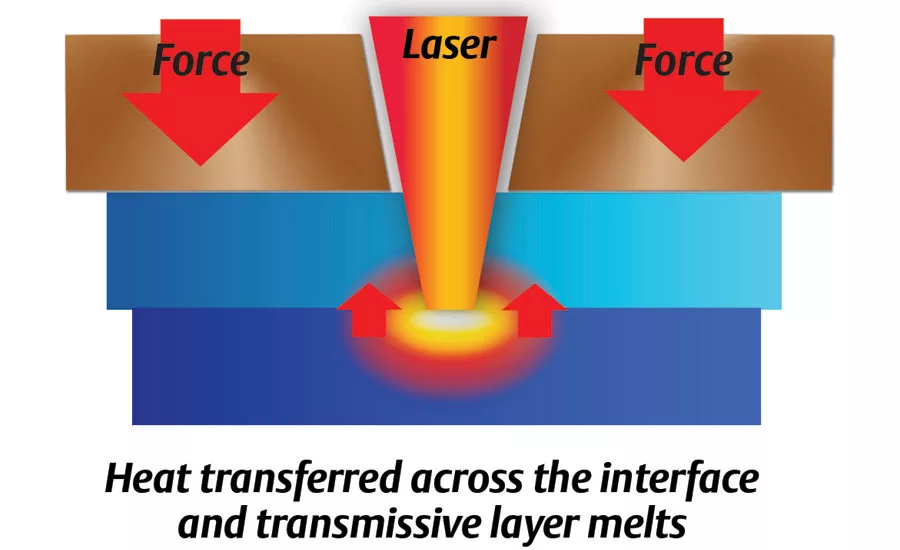
Figure 6: STTlr Laser Welding. This shows a laser welding system that includes the power supply, controls, and cooling system on the right along with the actuator and laser banks on the left.
Whether you’re choosing an assembly method for a newly developed product or reevaluating the effectiveness of a current assembly method in light of a change in product design, materials, or production mix, the thought process you’re undertaking is important. It’s a thought process that my colleagues and I have participated in with hundreds of individuals and organizations in dozens of industries. And it’s valuable because the key variables in assembly and joining operations—application requirements, customer needs, product designs and geometries, materials, and joining technology capabilities—continue to evolve rapidly in ways that impact the cost, competitiveness, performance, and quality of your operations and your products.
There are three main categories of methods used to join or assemble parts made from plastic components: mechanical, adhesives and welding.
Mechanical joining methods include, but are not limited to, snap- and press-fit joints, screws, and rivets. These methods typically are selected when plastic products are subject to disassembly during their working lives. All sorts of mass-produced products may require some disassembly to allow for everything from simple battery, bulb, or filter changes to more complex repairs involving circuits, components, or screens in everything from cell phones or other small devices to appliances, computers, even automobiles. But beyond these mass-produced items, mechanical joining methods can also be cost effective in low-volume applications where the cost of capital equipment for joining components exceeds the cost of the labor and mechanical fasteners needed to reliably assemble the product.
Adhesives are another popular method for assembling or joining plastic components, and are one of two “permanent” joining methods. Adhesives are most commonly used in applications where the plastic components to be joined are made of materials that are not compatible. By not compatible, I mean that their physical and melt characteristics are different enough that they cannot be reliably joined using plastic welding methods that involve heat and pressure. One example would be joining a flexible PVC medical tube to a rigid plastic valve.
There are many types of adhesives that can be used in a wide variety of applications. For optimum results, you should contact an adhesive manufacturer to determine the best product for your application. As with mechanical joining methods, you will need to consider the cost of the consumable—the adhesive—as well as the cost of the tools or dispensing machinery needed to apply it. Depending on the type of adhesive being used and the size and configuration of the parts being joined, you also may need to invest in some kind of fixturing to hold the parts in place until the adhesive bond cures to full strength.
The other “permanent” methods for joining plastic components involve plastic welding, which uses a combination of heat (or friction-generated heat) and pressure to join plastic components. Plastic welding methods are ideal for assembly when the plastic materials being used are compatible with each other and the process and the application requires a permanent or tamper-proof seal between the components. Unlike both mechanical and adhesive joining methods, plastic welds do not use consumables like fasteners or glues. The only incremental cost for welding involves the initial capital investment required to purchase a plastic welder, plus the cost of electricity to run it.
Plastic welding isn’t one technology—the term encompasses a range of joining technologies that continue to evolve to meet a wide range of assembly needs. In rough order of their popularity and usage in the marketplace, plastic welding technologies include:
- Ultrasonic Welding
- Vibration Welding
- Laser Welding
- Infrared Welding
- Spin Welding
- Thermal Processing
- Hotplate Welding
Ultrasonic welding
Ultrasonic welding is an extremely popular and cost-effective assembly technique. It utilizes a series of components—a power supply, converter, booster, horn and actuator—to deliver mechanical vibration and force to the parts being joined. The high-frequency vibration generated by these components produces heat at the interface of the parts to be joined, melting the plastic and creating a strong bond.
Looking for quick answers on assembly and manufacturing topics? Try Ask ASM, our new smart AI search tool. Ask ASM
Figure 1 shows how the power supply, converter, booster and horn function together to create mechanical vibration. The power supply takes standard electrical line voltage and converts it to an operating frequency (in this illustration – 20 kHz). Power supply frequencies are set, but are available between 15 – 70 kHz. The most common frequencies are: 20, 30 and 40 kHz. This electrical energy is sent through an RF cable to the converter. The converter utilizes piezoelectric ceramics to convert the electrical energy to mechanical vibrations at the operating frequency of the power supply. This mechanical vibration is either increased or decreased based on the configuration of the booster and horn. The proper mechanical vibration, known as amplitude, is typically determined by an applications engineer and based on the materials being welded.
Figure 2 shows is a typical bench type ultrasonic welding system. The actuator base and column can be removed which provides an excellent configuration for integrating into automation. The actuator is used to deliver the converter, booster and horn (commonly known as stack) to the parts being welded and applies force. Weld forces can range between 50 to 750 lbs. The actuator can also have other components such as a linear encoder to measure weld distance.
The key benefits of ultrasonic welding as an assembly processor are: speed (most weld cycles are completed in less than a second), no consumables, no part set-up times, a low capital equipment cost, and easy integration/installation as part of automated processes. The limitations of ultrasonic welding center on the materials being welded, the size of the parts, and the geometry of the parts. For materials that are “easy” to ultrasonically weld, such as ABS, parts up to 10 x 10 inches can be joined with a 15 kHz ultrasonic welder. When parts are made of materials that are more difficult to ultrasonically weld, such as Nylon, the size of the part to be welded decreases down to about 3.5 inches square (or diameter). Parts with deep contours may also prove difficult to weld, since these features can affect the range and performance of the ultrasonic process.
Vibration (and “Clean Vibration Technology”) Welding
Vibration welding is a close cousin to ultrasonic welding. It is accomplished by holding one component in place, holding the mating part against it at a precisely determined pressure, then applying a reciprocating linear motion to the mating part. The friction created by the motion of the mating part melts the adjoining surfaces, and when the motion concludes, the welder returns both parts to their original positions so that the bond between them will cool in a properly aligned position. The frequencies used in vibration welding are considerably lower than in ultrasonic welding, ranging between 100 to 240 Hz, but the amplitude of the vibrations is larger, ranging from 0.030” to 0.160.”
Vibration welding has many benefits. It can join parts made of virtually all thermoplastic materials (crystalline, semi-crystalline as well as amorphous), as well as parts with larger sizes and more complex shapes. The process is very tolerant of the “heat history” of a material, which may include additives, colorants, fillers and even environmental contaminants such as dust, paint, or grease. And, the process doesn’t affect internal components such as printed circuit boards. The process and its tooling are scalable, so many parts can be welded in a single cycle, and it requires relatively low amounts of energy. Vibration welding also produces parts with high strength, leak-tight seals that protect against a wide range of contaminants such as dust, water, blood, toner, ink, helium and other gases. And, the process is relatively forgiving, in that it allows for “corrective” melting and bonding of plastic parts even when they have relatively high part-to-part inconsistency.
The limitations of vibration welding are mostly related to the ability of the part designer to incorporate the features required for the process. Because mechanical friction is used to create the weld, the design of the parts must allow for relative motion between the mating surfaces of at least 0.070” peak-to-peak. Part walls that are perpendicular to the vibration motion must be robustly designed so that they will not flex during vibration. Depending upon the size of the weld and the depth of melt, vibration welds may produce a large amount of flash. However, if weld flash must be concealed to meet with the aesthetic requirements of the finished part, a flash “dam” or “trap” feature can be incorporated into the part design, though such a feature adds to the surface area and material requirements of the part. Loose internal components can be incorporated in the stationary, non-vibration side of the tooling but these parts must not interfere with the mating part. Internal walls that are perpendicular to the vibration direction may not weld if not properly gusseted or otherwise stiffened. While the weld plane does not have to be flat (a 90° angle can be welded if the part is vibrated with the curve oriented parallel to the vibration direction) the part must be able have relative motion in at least one plane. A parabolic part such as an automotive headlamp may be curved in both the X and Y axis and therefore not be a candidate for vibration welding.
Recent advancements in vibration welding have led to a hybrid approach that combines standard vibration techniques with an additional, infrared heating source. This approach, called clean vibration technology, utilizes an infrared heat source to precisely preheat the weld surfaces, then removes it before the surfaces are vibration welded together. This approach offers the advantages of vibration welding, but reduces the amount of vibration required to achieve the melt. Thus, the formation of flash and particulates is dramatically reduced, as shown in Figure 5.
Except for the additional time and equipment required to accomplish the infrared heating step, CVT is essentially similar to vibration welding in terms of part loading and handling. However, the cycle times are extended, typically from three to five seconds for a vibration weld to 25 to 40 seconds for a CVT weld.
Laser welding
Laser welding is a gentle, clean, and precise joining process that enables the welding of complex geometries and materials that are difficult to bond with other common plastic welding techniques. Unlike the ultrasonic and vibratory weld methods noted above, laser welding requires no motion, no friction between the components being welded. The heat needed for part welding is infrared, provided by a laser light source. Since no relative movement is required between the parts, weld alignment and part-to-part sealing is exceptionally precise. Welds are perfectly clean, with zero particulate and zero flash.
An innovation to laser welding, called simultaneous through transmission infrared welding (STTIr), is the first laser welding technology that can illuminate the entire welding surface at the same time. This approach eliminates the need to move, or “scan” heat sources along the length of the weld and thus dramatically speeds up the laser welding cycle, reducing it to as little as five to seven seconds. The exceptional cleanliness and precision of laser welding is the primary factor behind its recent and rapid growth in medical device, consumer electronics, high-end automotive, and business applications.
STTIr laser welding has certain part design requirements. First, one component of the assembly must be “transmissive” or “clear” to the laser wavelength to be used, while the mating component must be “absorbent” or “black” to that wavelength. Second, the geometry of the assembly must allow for delivery of the laser energy to the weld zone, where the melt occurs in the upper section of the absorbent part.
Laser welding equipment typically consists of a stand (or a larger rack) that holds one or more laser light sources, or diodes, typically in the 780 to 980 nm range. The light from these sources is concentrated and delivered to the parts through fiber optic bundles that are arranged around the perimeter of the part to be welded. The laser output from each diode is distributed over the weld area of the part according to the heating density required by the application.
Like other types of plastic welding, laser welding utilizes tooling to hold the parts that are to be joined. The key difference in tooling for laser welding is that the fiber bundles must be linked to the tool. Fortunately, this is a straightforward process since the output sections of the fiber bundles are manufactured with circular ferrules or other features that are easy to incorporate into the tool.
Figure 6 shows a laser welding system that includes the power supply, controls, and cooling system on the right along with the actuator and laser banks on the left. The system can be mounted on a bench or easily incorporated into automation.
Meeting the requirement of having one part that transmits laser light and another that absorbs the light need not be difficult. There are many “clear” plastic materials, as well as colored pigments that properly transmit laser light despite the fact that the parts made from them appear pigmented to the human eye. The same holds true for absorbent parts. Beyond the obvious—carbon black—there are a wide range of color pigments that absorb laser light, resulting in parts that are laser-weldable. To be sure your combination of part colors and pigments work properly, just consult with your weld equipment supplier.
This is part one of a two-part series.
Looking for a reprint of this article?
From high-res PDFs to custom plaques, order your copy today!