Optimizing Ultrasonic Plastic Welds
This advice should assist you in solving day-to-day ultrasonic welding challenges
There’s nothing better than starting an ultrasonic plastic welding application and finding the process “window” right away—the sweet spot in which people, parts, equipment and processes run smoothly, with great yields and timely, efficient production.
Sometimes, however, it is necessary to take on a new process or a new machine that isn’t quite dialed in yet. Maybe a new ultrasonic welding unit—or a dozen units—have just arrived from the factory. Maybe an existing machine has just been relocated from another process and must be configured to match up with other welders. Or, perhaps you’ve got a machine or two—or an operator or two—that are just not quite right.
In such cases, engineers will need to dial in the ultrasonic welding process, adjusting amplitude, force, speed and other parameters until the process is just right. This article will guide you through that process.
First, however, we’re going to make a few assumptions:
- You’ve got a well-designed part that’s properly dimensioned and made from a weldable material.
- You’ve developed a “golden part,” a production part that is correct in all dimensions. You may do this on your own or by working with your welding vendor.
- Your welding vendor has provided you with a recommended welder, weld mode and parameters, plus tooling to produce the part. The welder is complete, including power supply, booster, actuator (with a properly sized cylinder), upper tooling (horn) and lower tooling (anvil).
Overwelds and Underwelds
Start by understanding what a good weld is. A good weld produces a finished assembly that meets dimensional tolerances, strength requirements, sealing requirements and cosmetic requirements. It does these things within an acceptable cycle time and with an acceptable yield. A “bad” weld is one that fails to meet one or more of those requirements.
To describe bad welds, we’re going to use a couple of terms, “underweld” and “overweld,” then suggest ways to optimize your welds until they are “just right.” An underwelded assembly will show signs of inadequate melting and uneven or off-level joints. It will fail strength tests and sealing tests. An overwelded assembly will exhibit excess flash, part bending or deflection, and part marking or embossing.
A properly designed part is typically designed with a joint containing some type of energy director—a structure designed to concentrate weld energy and melt first. The energy director provides a focal point for the ultrasonic energy. Under vibration and downward force, it melts to form a pool of molten plastic that, after cooling, should firmly weld the part together, providing adequate strength and sealing. The “collapse” that occurs when the energy director melts is often part of a critical dimensional tolerance for the welded assembly, particularly if that assembly must fit into, or integrate with, surrounding parts or assemblies. For example, if the energy director is 0.02 inch tall, the collapse depth of the weld would be set to 0.018 inch or so, enabling the hot plastic and down force to do the rest.
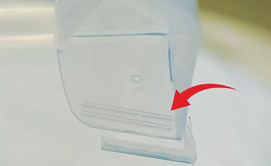
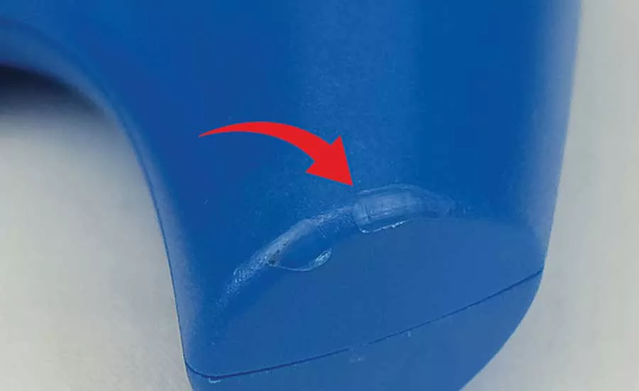
As an example, let’s look at the handle of a plastic beverage pitcher (see figure 1). On the underside of the handle, there are a pair of energy directors on both the top and bottom of the handle. Each energy director is a triangular bead of plastic that helps weld the handle to the pitcher itself.
Looking for quick answers on assembly and manufacturing topics? Try Ask ASM, our new smart AI search tool. Ask ASM
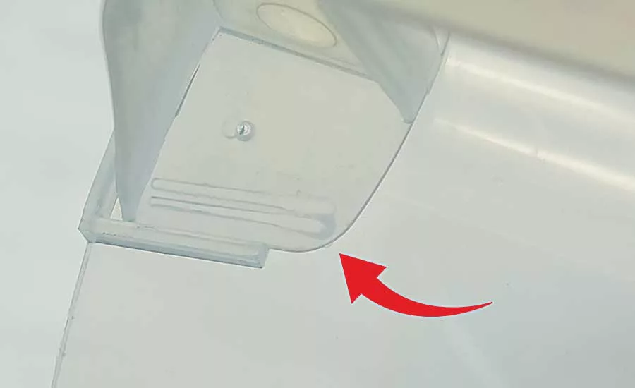
After putting in the factory parameters and welding a few samples, you note a pattern—an underweld (see figure 2). The underweld is severe: The energy director is just beginning to melt at the right side, but hardly touched on the left. Because we know that you are working with good parts, this defect has two likely causes. First, the base of the welder (the “anvil” that holds the pitcher) may be off level, so when the horn is actuated, it does not press evenly on the handle when the weld begins. Alternatively, it could be that not enough energy is going into the weld to melt the entire energy director.
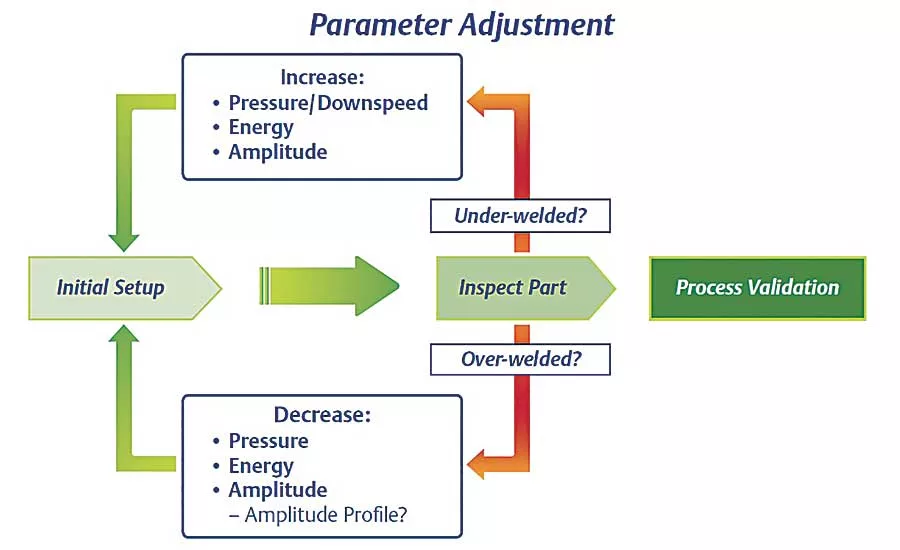
To correct the weld, begin by inspecting and adjusting the level of the welder table, then ensuring that the horn is making consistent contact over the entire length of the intended weld. Then, increase the amount of time or energy going into the weld.
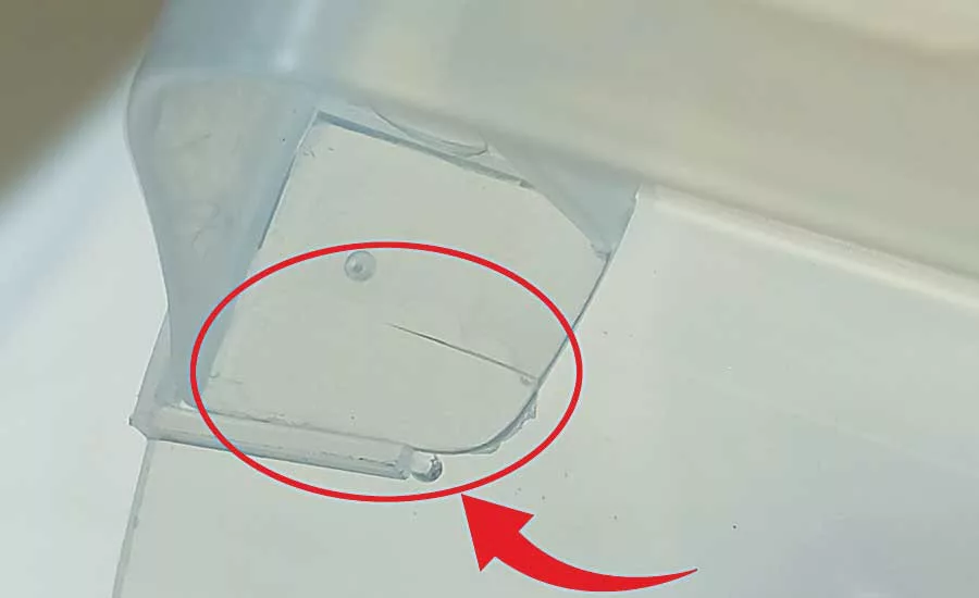
After correcting the level of the equipment and adjusting weld energy as required, commercially acceptable welds are produced (see figure 3). In these good welds, the energy directors essentially disappear, spreading out into a consistent “puddle” of molten material along the entire length of the joint. This molten material firmly bonds the handle and pitcher together.
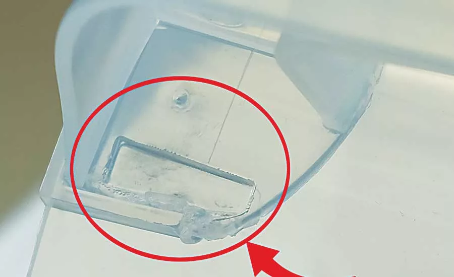
Now, let’s look at the same assembly, only this time, the issue is overwelding (see figure 4). Too much weld energy and force have been applied to the parts, resulting in an assembly that is severely marked—essentially embossed—by the horn.
Figure 5 shows another example, the plastic handle for a medical instrument. The handle is a two-piece assembly with an energy director on the inner surface of the upper part. The joint appears to be melting fine, producing what appears to be a strong joint. However, the assembly has a cosmetic problem: The horn is marking the curved edge of the part, damaging the textured surface and leaving a shiny area.
Both of these problems are overwelds, usually the result of exerting too much downward force on the part or applying too much energy to the part. Once the energy director has melted, the extra energy has nowhere to go, so it concentrates on the part surface, where the marking occurs.
To optimize the medical handle weld, start with a pull test to check the strength of the weld. Then, cut the part open and inspect the welds inside. If the part is marked, but the interior does not show excess flash, a modest adjustment, such as a slight reduction in amplitude is in order. If the weld exterior is marked and the internal joint shows heavy flash, a more substantial adjustment is needed. Try reducing weld time, weld energy, downward force, or some combination of the three.
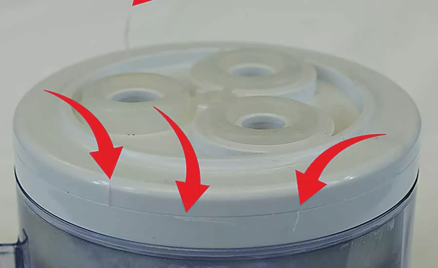
Let’s look at another example, a two-piece filter assembly for a medical device (figure 6). The weld for this part has good strength, but produces a wispy flash at the parting line. This overweld indicates that the process is melting too much plastic, too much downward force is squeezing out the flash, or both. Correcting this weld shouldn’t require too much in the way of change: perhaps a small reduction in weld amplitude or down-force.
Making Adjustments
To optimize welds, it is important to understand weld control modes, weld parameters and the degree to which adjusting them changes the welding process. Some of these adjustments are fairly large or “coarse,” while others are “fine,” having a more subtle influence over the process.
Adjusting the level and alignment of the system and tooling would be an example of a coarse adjustment. Ensure the anvil is level with the horn, and the horn is aligned with the part. Adjust the weld table and tooling as necessary.
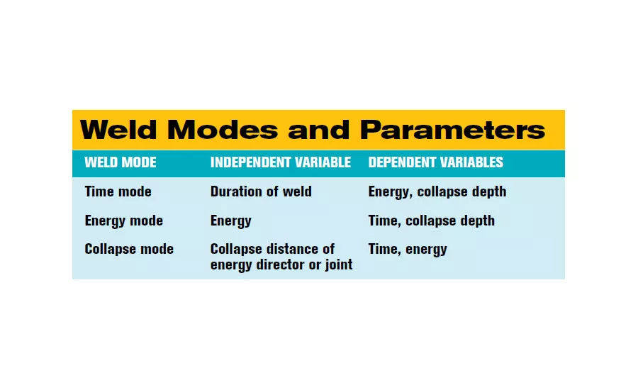
Weld mode parameters would also represent coarse adjustments. Ordinarily, weld optimization does not require the changing of weld modes, which are usually recommended by the weld vendor as part of a basic set of production parameters associated with a specific application and parts. However, there are parameters within each of these modes that can be changed as part of an optimization process for significant overwelds and underwelds. The three most important control modes are time, energy and collapse.
Correcting overwelds may involve reducing weld time, energy or collapse distance. Similarly, optimizing underwelds may require increasing weld time, energy or collapse distance. If you decide to make parameter changes, work with one parameter at a time, so that you can gauge the impact of the change.
If your process does not allow for a detailed design of experiments approach, an alternate method of optimization involves making a sizable parameter change, perhaps 20 to 30 percent, so as to induce the opposite failure. In other words, if you’re overwelding, try to induce an underweld. You then know that the solution lies somewhere in between, and you can, through subsequent welds, hone in on an optimal result. Note that adjusting parameters in much small increments is an alternative, but the small changes that occur can make it harder to recognize an optimal result.
If your weld problems are relatively small, such as mild part marking or flash problems, then weld optimization will require relatively fine adjustments to other parameters used in the welding process. These include:
Gauge pressure, down-speed and trigger force. These parameters affect the downward clamping force that is exerted on parts before and during ultrasonic welding. Gauge pressure is the level of air pressure operating the air cylinder in the actuator. Down-speed regulates the rate at which the horn descends to engage the parts and build up clamping force. Trigger force is the force of horn contact on the parts that is needed to initiate a weld.
If these forces are too high, parts may deflect or bend under the tooling impact, or overwelds with marking or flash may occur. You can adjust down-speed to slow the descent and clamp force buildup of the tooling on the part, since “hitting” or “squeezing” the part too fast or hard can cause part marking. Similarly, too much trigger force can cause part marking, while too little can cause uneven or incomplete contact and welding of the energy director along the line of the joint. Note that both down-speed and trigger force may be adjusted separately from gauge pressure. However, without these adjustments, increasing gauge pressure increases the rate at which down-speed and trigger force are applied. It also speeds up cycle time.
Amplitude. If you’re close to a good weld, optimization may just require a tweak to either amplitude or down-speed. Amplitude is the range of vibratory motion suited to the material in the part. For example, the amplitude range for polycarbonate is 50 to 100 microns. For mild overwelds, consider reducing amplitude by 20 percent or so to induce an underweld condition. Then, gradually increase amplitude until you find the optimum setting.
Peak power output. This indicates the percentage of the total power supply output that is being used on the weld. If your welder has been properly sized, an extremely high reading (90 to 100 percent) is probably a red flag, indicating that a part is misaligned and that the welder is pressing too hard to try to reach trigger force.
This advice should assist you in solving day-to-day ultrasonic welding challenges and keep your production running smoothly. Of course, if you encounter problems and you need more detailed assistance, your ultrasonic welding vendor is ready to help.
Looking for a reprint of this article?
From high-res PDFs to custom plaques, order your copy today!


