Prototyping Complex Harnesses
Designing, building and testing complex wire harnesses takes planning, attention to detail - and a good tester
Vehicles have become increasingly electrical over the years. This is not just power electronics, but also sensor data, communications and many other coordinated electrical signals. For aircraft or commercial vehicles, wire harnesses can be even more complex with hundreds of interconnection points.
Designing, building and testing such harnesses takes planning and attention to detail.
Once the scope of the work is known sufficiently, work can commence on developing the harness design. Apportionment of the functional content—that is, how features are distributed across the vehicle, the number and locations of electronic control units (ECUs), etc.—is best done using CAD software. With this information, we can identify specific connectors and set about routing the wires to individual cavities.
We will be guided by a few things during this stage of the work, one of which is the equation for the resistance of a wire: R=rL/A.
In this equation, R is the resistance of a wire; r is the resistivity of the conductor (measured in ohms per meter); L is the length of the wire; and A is the cross-sectional area of the wire.
We will use this equation to give us the amount of resistance associated with the wire. R goes up as length increases, but it goes down as cross-sectional area increases. Simulations can inform us how much loss of signal (or voltage) may be due to the wire harness length and cross-sectional area, along with the current that can be carried. This will help us determine the optimal wire gauge so that we can carry the current or deliver the voltage to the load and not lose too much signal due to the wire length. It will also help with bundling, or which wires can travel in the same space within one group.
With the bundling complete, we can use CAD tools to route the harness. These tools often have simulation capabilities that allow engineers to explore how the system works electrically and not just mechanically. For example, we can simulate load characteristics for wire harness elements to test assumptions that are invariably baked in the design.
Looking for quick answers on assembly and manufacturing topics? Try Ask ASM, our new smart AI search tool. Ask ASM
These tools may even be sufficiently sophisticated to simulate data bus or serial communications. In these instances, we can observe the electrical impact of the wire harness on the digital signals, noting attributes like signal rise time and general shaping as way of confirming the wire harness design will not have a negative impact on the signal shape and strength.
Prototyping
Contrary to what many may say, vehicle design projects do not consist of doing all the paper design before the next phase. The paper design will be the CAD models. Design verification, in part, will be accomplished via simulation.
Sooner or later, however, you will need a physical prototype of the harness. The shop that assembles the prototype is typically the shop that will eventually produce the finished product. From my commercial truck manufacturing experience, lead times for prototype wire harnesses can be eight to 12 weeks. If you pay a premium, you might get moved to the front of the queue. The other solution is to build the prototype harnesses in house, but that comes at a cost, too.
Either way, prototype harnesses will eventually be required to explore how the wiring will fit into the vehicle. You can learn a lot from playing with the prototype, such as what special tools might be required to install it or how to install the harness in the most efficient way possible. The prototype also represents a learning experience for the harness shop.
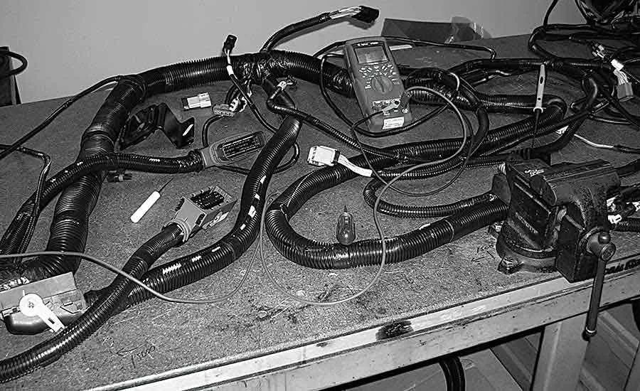
These interim builds of the wire harness will undergo physical examination. For example, engineers may double-check the lengths of the wires or perform continuity testing. These physical measurements tell us something about the actual part, and eventually these parts will be put into a test vehicle that’s close to the final production version. The data gathered from these measurements will have implications on future builds of the harness.
Continuity Testing
Dimensional and structural checks of the harness are not so difficult. However, continuity testing of the wire harness can be time consuming, especially for large harnesses that can consist of well over 400 wires. Commercial vehicles are not built like passenger cars. There are many variations and configurations of the electrical and electronic systems. For example, in some commercial vehicles, only the driver side has a power lock and power window.
Manually checking for continuity of a large harness bundle amounts to a spot check. Only a small portion of the wire interconnects can be cost-effectively tested via manual testing techniques before installing the harness on a test vehicle. As a result, it’s entirely possible for the prototype to have cross-continuity—wires that should not be connected, but are, in fact, connected.
To adequately check for such problems, we would have to test the expected connections along with unanticipated connections to other elements within the wire harness bundle. Since these wire harnesses will end up being used in prototype vehicles, it is important to ensure all these attachments are correct. From my time at a commercial vehicle manufacturer, we learned that it’s better to explore the wire harness in detail to assess the veracity and conformity to the design intent before the parts are installed on the prototype vehicle. A few minutes effectively testing a prototype wire harness can save hours and sometimes days in root cause analysis and rework at the vehicle level.
For example, let’s assume that a prototype wire harness has been built as designed and installed in a prototype vehicle. Next, we attempt to use the features of the vehicle only to discover that they don’t work. Why not? Is it errant software? Is it hardware? Or is it the wire harness? Invariably, all manner of engineers and technicians end up climbing into the vehicle to find out what is wrong. In some cases, a partial tear down of the vehicle may be needed to get to the harness with the problem and make corrections. This consumes many hours and keeps the test vehicle from track time or other testing activities.
So, how can we make this better? First, the harness prototype should be a known quantity before putting it on the vehicle. Continuity and other electrical testing must be done.
However, manually performing a point-to-point test of the wire harness is not an option. For example, let’s assume the harness has 100 connection points. Manually checking the continuity of one wire end to another can be done in perhaps 10 seconds. However, to test that one end for cross-continuity in a harness bundle of 100 ends will take 1,000 seconds—nearly 17 minutes.
This is not the best use of time, especially when this sort of testing can be easily automated. A good harness tester can check 100 wires in 1 second! With luck, a manual test might be 95 percent accurate. A harness tester can run the test with a 99.999999 percent accuracy rate.
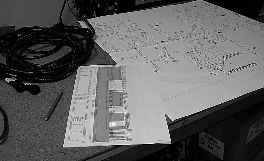
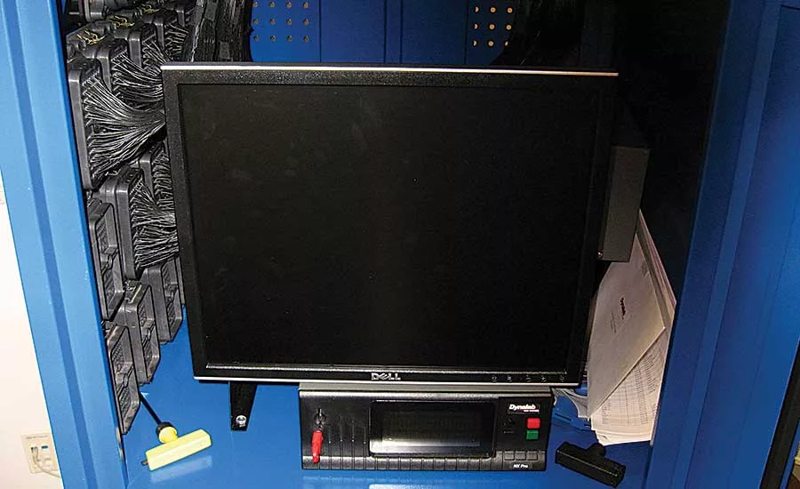
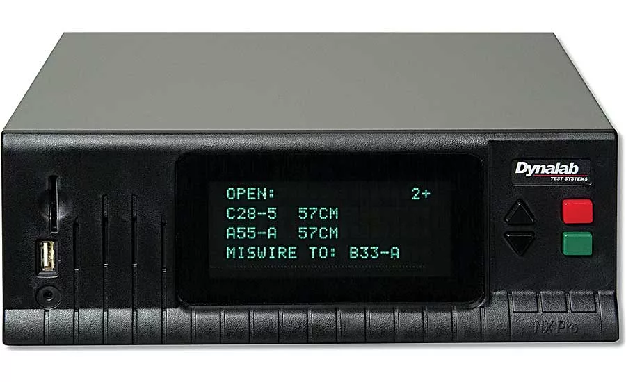
At the truck manufacturer, the harness tester we used was the NX Pro+ from Dynalab Test Systems. This instrument can import design documentation directly from the engineer’s computer into the test fixture, minimizing documentation handling errors. The fixture has 32,768 test points.
To test a harness, an adapter harness must be made to connect the test fixture to the wire harness. Next, a configuration file is loaded into the harness tester. This configuration file is the export of the wire harness design documentation. It contains a list of all the harness test pins, as well as the design of the harness itself. This fixture then compares the harness to the design documentation in seconds. The instrument checks for continuity, discontinuity and cross-continuity faster and more accurately than can be done manually. Additionally, the instrument can detect intermittent wire connections, providing the specific locations where the harness loses connectivity.
Of course, a harness tester is not infallible, either. The configuration file feeding the harness tester must be correct, so examining the process to create the configuration file can lead to additional time savings. Creating this file by hand is not the most efficient use of engineering time. In one case, it took at least five hours to create one configuration file. Ultimately, we developed a simple program that reduced the execution time to about 5 seconds. It took two days to create the program, for a payback after about four harnesses.
If your product consists of large wire harnesses, you would do well to find ways to automate the comparison of the product to the design intent.
Looking for a reprint of this article?
From high-res PDFs to custom plaques, order your copy today!


