CAD Software Aids Assembly
Next-gen CAD software lets engineers design a part or subassembly, then use simulation to create a virtual prototype of the final product.
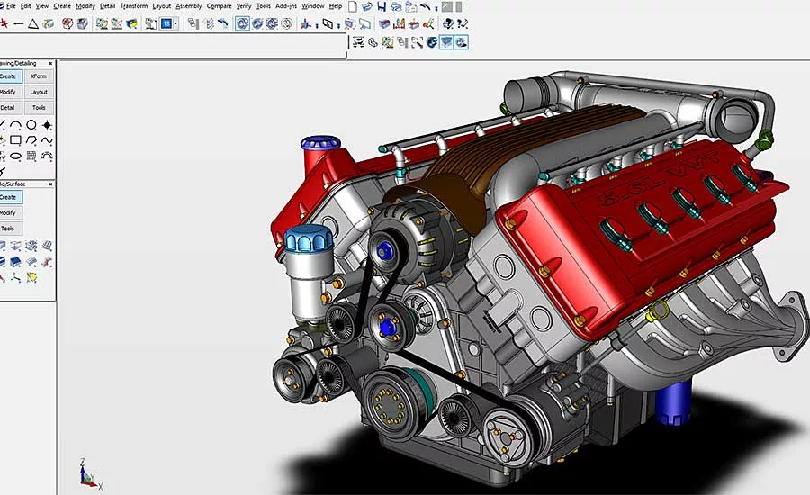
Computer-aided-design (CAD) software has a been friend to part designers and manufacturing engineers for decades, which is old news. The good news is this type of software is friendlier than ever, enabling both specialists to perform functions ranging from analyzing the strength of an assembly, to determining the best design for a given set of parameters.
“CAD software has evolved way beyond simply designing a part,” explains Bob McGaughey, senior applications engineer at Computer Aided Technology Inc. (CATI), a value-added reseller of Dassault Systemes SolidWorks Corp. software. “Three-dimensional software provides all-encompassing product development, including sketching, designing and simulation modeling to create virtual prototypes.”
Smartphone manufacturers regularly use CAD software to build the most durable device, notes McGaughey. The software user begins by determining the components of the phone and how they will fit together.
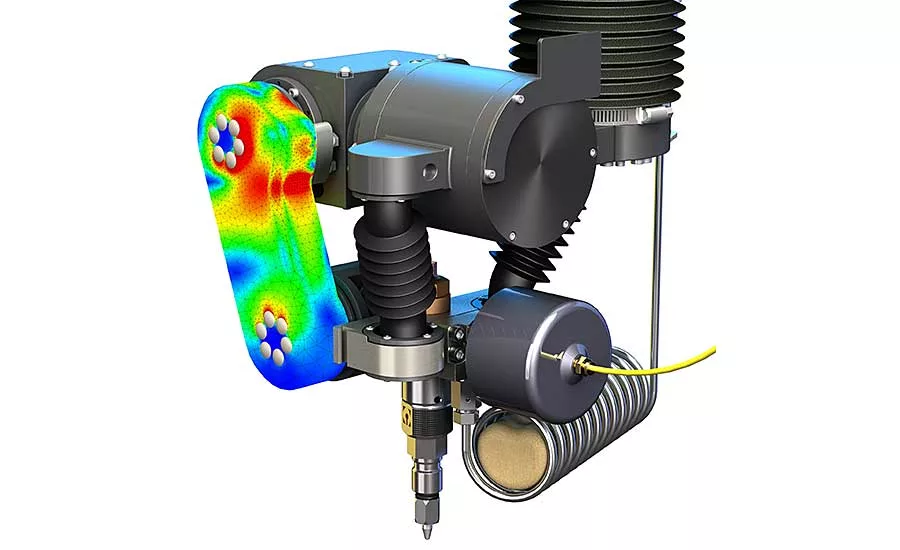
“He or she then must address the question: what happens to the phone when it gets dropped?” says McGaughey. “For that answer, a dynamic finite element analysis (FEA) of each phone-component material is done, as well as that of the floor material. Related questions include how far will the phone drop to the floor and at what angle? Using exact physics parameters, the software accurately determines the shock wave and force that go through each part in the phone immediately and a few seconds later.”
CAD software also helps engineers quicken equipment design. British farm equipment manufacturer Claydon Yield-Meter Ltd. can attest to that.
By using SOLIDWORKS’ Treehouse editing tool, Claydon’s engineers are able to visualize the project structure of an assembly, as well as create a project hierarchy by mapping out and tracking its components and subassemblies. They can also make changes to file properties and configurations, and perform file suppression.
Success stories like this are commonplace in manufacturing, and will be for years to come thanks to CAD. In just a few decades, the software has become the must-have tool for anyone who needs to accurately design parts and subassemblies. This capability, in turn, helps optimize the downstream assembly process of all products, regardless of their component material, size, geometry and end use.
Looking for quick answers on assembly and manufacturing topics? Try Ask ASM, our new smart AI search tool. Ask ASM
A Solid Track Record
Over the past 27 years, SOLIDWORKS CAD software has evolved and expanded to offer users many important capabilities. SOLIDWORKS uses parametric solid modeling, and it easily works with all other CAD-based Dassault products. These are CATIA (a CAD/CAM/CAE/PLM/3D platform), DELMIAWorks (enterprise resource planning system), Simulia (multiphysics simulation), eNovia (product lifecycle management system), NetVibes (marketing data aggregator) and SOLIDWORKS Marketplace (supplier collaboration).
The software is great for designing products that contain hundreds or even thousands of parts, according to McGaughey. It lets users simply create drawings, parts and subassemblies, as well as quickly open complete assembly files or only those for specific parts. Equally important, engineers can share large designs in small files, while still protecting the company’s intellectual property.
The latest version, SOLIDWORKS 2021, features the 3DEXPERIENCE platform, which is cloud based and allows all members of a design team to easily access all project-related data. “3DEXPERIENCE has allowed us to be the virtual company we initially desired to be,” says J.P. Judge, owner of Acer Technologies, which designs and manufacturers electrical enclosures.
Acer engineers primarily use the SOLIDWORKS Sheet Metal, Electrical, Drawings and Flow Analysis features in their work, and then 3DEXPERIENCE to manage everything. Sometimes they use Model Based Definition for documentation and SOLIDWORKS Composer to create animations of how customer assemblies are built to work.
“Our approach to helping engineers design parts and subassemblies is through concurrent engineering, rather than linear progression,” notes McGaughey. “The latter refers to the traditional method of one person doing the design, and passing it on to the next person to do simulation, and passing it on to the next person to create assembly instructions and related data, etcetera.
“Concurrent engineering utilizes a constant feedback loop that allows for simultaneous design, testing and document creation,” continues McGaughey. “There are always going to be changes during the design process. The benefit of the concurrent method is when you change one thing, everything else changes, thereby ensuring that everyone has access to the latest model version and data.”
Direct Success
It is well known that engineers use CAD software to design parts, subassemblies and products. Less well known, but no less important, is their need to also design tooling, which is anything that touches a part during the assembly process.
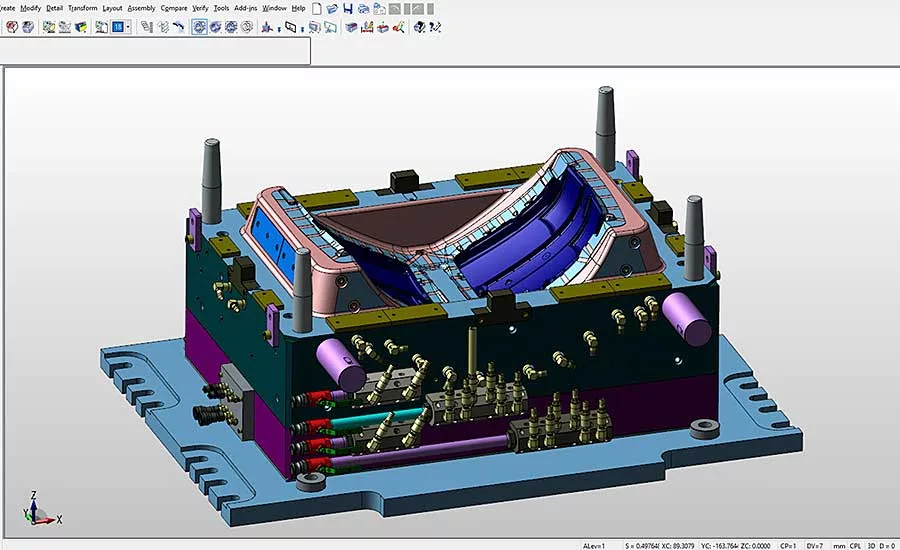
“For end-users of our KeyCreator MFGCAD software, tooling includes molds and fixtures that keep components in place,” explains John McCullough, marketing general manager at Kubotek3D. “Automotive engineers especially like how our software lets them design molds for complex and deep plastic parts like taillights and large parts such as dashboards.”
KeyCreator MFGCAD runs on Windows in a standard PC and uses direct solid modeling. It also is able to reuse CAD data from any source—including other software such as SOLIDWORKS, CATIA, PTC Creo and Siemens NX.
“Our direct-modeling approach eliminates the constraints that come with saving the full work history of a project,” says McCullough. “It really is simpler for engineers. They work strictly with pure geometry and can add new values to the model as needed. Plus, there are no limitations to the types of parts and products that can be designed in terms of shape and complexity. CNC-machines parts can be designed as well.”
The automotive industry has been the biggest user of MFGCAD over the past 20 years or so. Engineers in aerospace, medical devices, consumer electronics and roll forming like the software as well. Aerospace engineers find the software particularly helpful when designing molds for vacuum-formed interior parts, notes McCullough.
“The 3D solids capabilities in KeyCreator can solve complex assembly challenges and create assembly instructions,” says McCullough. “Beyond basic visualization of assembly fit, KeyCreator lets manufacturing engineers project the shape of 3D solids along assembly paths and test for interference with neighboring 3D parts.”
Louisville, KY-based Cardinal Manufacturing, a custom roll forming company, has used KeyCreator for several years. Manufacturing engineer Kenneth Harris tells of receiving one order for tooling to produce a roll formed ring (similar to a hose clamp). The ring started out with a single profile and a single diameter, but over time the order has resulted in 13 different profiles—each of which requires up to 25 different diameters.
“With KeyCreator, we were able to modify the models and produce completely new designs for the set of tools in less than four hours,” says Harris. “Previously, those changes and redesigns would have taken two to three weeks.”
Versatile Enough for Equipment and Parts
Designing machines is very different from designing parts, yet IronCAD LLC’s software is versatile enough to help companies that need to perform either task. Founded in March 2001, IronCAD includes numerous 3D modeling tools in its Design Collaboration Suite (DCS) to significantly improve the productivity of designers and engineers.
“About two-thirds of our customers use the software to design machines or for metal fabrication or tooling,” notes Cary O’Connor, vice president of marketing at IronCAD. “The other third uses it for a variety of tasks, such as to designing furniture or ship interiors, or for artistic purposes.”
O’Connor says the DCS is an MCAD software that uses configuration-based design. This unique approach lets an engineer select parts or subassemblies from a catalog, and then drag and drop them into place to create a model. This model, in turn, uses smart eBehavior, which contains intelligence and domain-specific knowledge on each part to automatically position them.
“This intelligence precisely positions, sizes and orients one part onto another part,” explains O’Connor. “You can even add behaviors, such as predefined constraints, that provide accurate movements in mechanisms or other positioning commands.”
The software’s Unified Design Environment gives engineers the flexibility to decide how they’d like to go about creating and changing their assemblies, no matter where they are in the design process. Users can group common components and quickly search for desired parts in a design, as well as easily share relevant content such as materials and catalogs among the design team. Three-dimensional drawings of completed parts and assemblies are stored in libraries.
Designers use all or parts of the suite as needed, with IronCAD being the main component. Others include IRONCAD Draft (2D data and views), INOVATE (simple 3D concept design) and COMPOSE (3D data viewer).
Modular display system manufacturer Abstracta has used IronCAD for the last several years to fully automate its in-house sales process. As inquiries come in over the phone, sales teams quickly and easily build virtual shelves by using the IronCAD catalog of standard parts for the display system.
The teams create photorealistic renderings, generate detailed site-installation drawings, calculate shipping weights, and produce an accurate bill of materials data, costing information and picking lists. O’Connor says that quotation time has been cut from hours to minutes, with sales increasing by up to 20 percent, and associated costs and errors being noticeably reduced.
All You Need is Data
The features, benefits and capabilities of 3D CAD software are quite impressive. But, for some manufacturers, they are excessive—in the same way that a luxury vehicle is excessive compared to a microcar. The latter gets you where you need to go, but without any bells and whistles.
“CAD is a powerful tool that needs a powerful processor,” says Erik Freeman, director of sales and partner development at Lattice Technology Inc. “But when it’s used to design a model of a large product, such as a vehicle that contains hundreds or thousands of parts, the file being worked on may take up to several hours to load. Having the designer just sitting around during this time limits his productivity and is expensive for a company.”
XVL software from Lattice eliminates this production bottleneck by enabling engineers to quickly convert 3D CAD data to an .XV2 or .XV3 file and then repurpose the file to any manufacturing department that needs it. Equally important, the software compresses original CAD data files as large as several gigabytes to an average 1 percent of their original size, while maintaining high accuracy (up to 0.001 millimeter).
Freeman notes that XVL is CAD-agnostic and lets engineers import models from CAD software such as CATIA, SOLIDWORKS, NX, CREO and AutoDesk Inventor into a single file. This file can then be used to author content that is useful for downstream functions, such as service or assembly. It can also be managed by XVL Contents Manager to add revision control capabilities in downstream functions, and to manage very large sets of XVL data.
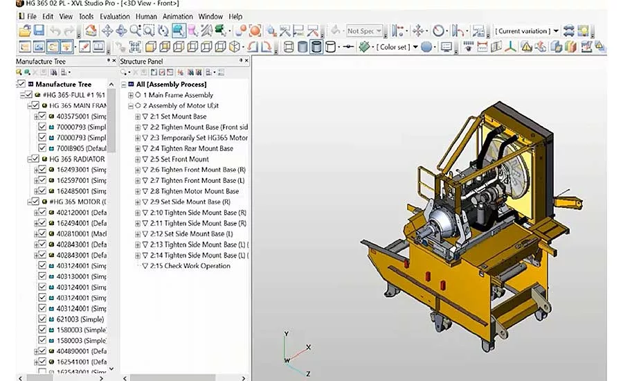
“After data conversion, the engineer uses XVL Studio to plan the entire assembly process, step by step,” explains Freeman. “During this process, he can create the manufacturing bill of materials, which allows for an alternative, but logical, workflow.”
Mitsubishi Mahindra Agricultural Machinery (MMAM) uses XVL software to design its tractors and combines. Company managers like that they can use 3D models to check the progress of assembly work at any point in the process, and that the software makes it easy to pass down production preparation skills to younger employees.
With XVL, the company is able to produce equipment as fast as it is sold, enabling line managers to quickly switch from the conventional method of lot production to mixed production of diverse products. The software also prepares general work instructions that MMAM adjusts to each manufacturing site and assemblers can refer to on paper, laptops and tablets.
Looking for a reprint of this article?
From high-res PDFs to custom plaques, order your copy today!


