Software Aids Design of Wire Harness for NASA's New Rocket
NGIS increases cable design productivity for NASA rocket by moving to a digital design process
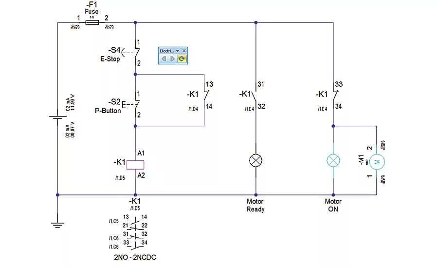
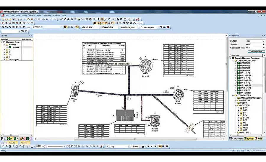
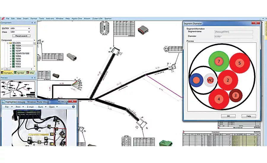
The data generated in E³.series projects provides intelligence to enable automation of many downstream activities. Photo courtesy Zuken
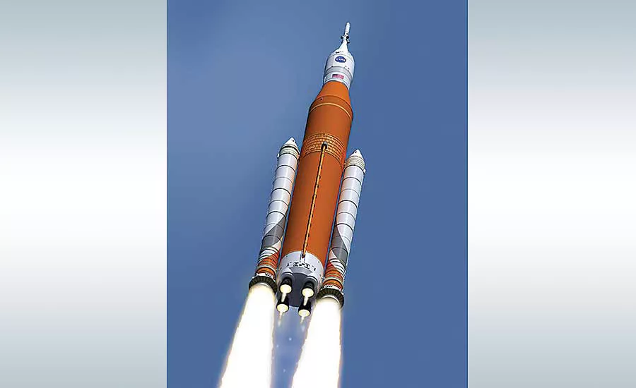
If astronauts ever set foot on Mars, they’ll get there with the help of NASA’s Space Launch System (SLS), the most powerful rocket ever built.
The SLS is designed to take astronauts further into space than ever before and provide the cornerstone for future human space exploration. Intended to replace the Space Shuttle, the SLS will have a total thrust greater than that of the Saturn V, the rocket that took astronauts to the moon. The initial version of the SLS, known as Block 1, will be able to lift a payload of 95 metric tons to low Earth orbit (LEO). A subsequent version, Block 2, will be able to put 130 tons into LEO and beyond. The rocket’s maiden flight is currently scheduled for June 2020.
The solid rocket boosters for the SLS are being designed and built by Northrop Grumman Innovation Systems (NGIS), which was previously known as Orbital ATK Inc. NGIS is the world’s top producer of solid rocket propulsion systems and a leading supplier of military and commercial aircraft structures. It also manufactures satellites and satellite subsystems; lightweight space structures, such as solar arrays; flares and decoys; and low-cost, quick-to-market launch vehicles.
The SLS boosters will be mounted on either side of the core stage and provide approximately 80 percent of the initial thrust needed to leave Earth’s orbit. After a two-minute burn, the disposable boosters will fall into the Atlantic Ocean.
The booster will be approximately 177 feet long and weigh 1.6 million pounds (the propellant accounts for 1.5 million pounds). To date, the booster has undergone five successful static-fire tests.
Classic Approach to Design
Launch vehicles and booster rockets are highly complex machines. They have innumerable mechanical and electronic components—all of which must endure the most extreme conditions imaginable with the utmost reliability. Just consider the guidance system: Imagine the technology required to maintain control of a car with the cruise control set to 17,000 mph!
And yet despite that complexity, some surprisingly “old school” methods are sometimes used to design them. Initially, NGIS was contracted to design the first stage of NASA’s Ares I launch vehicle, a predecessor concept to the SLS. To design the wire harness for the stage, NGIS engineers used a “classic approach,” recalls Nathan Holyoak, product life cycle management strategist for NGIS.
Looking for quick answers on assembly and manufacturing topics? Try Ask ASM, our new smart AI search tool. Ask ASM
Technicians built a full-size mock-up of the Ares first stage and ran rope through it to simulate cable runs. Wooden boxes were used to simulate electronic subassemblies. Different diameters of rope helped determine how many wires would fit in a given area.
All this information was then captured in a massive spreadsheet that was used to store information on each cable and perform a variety of calculations, such as voltage drop. Electrical schematics were created using Microsoft Visio, and mechanical computer aided design (MCAD) drawings were created using the Siemens NX CAD system. To accommodate the harness, the drawings included a fixed-diameter “sweep” along a spline in the stage. (Such a sweep is often referred to as a “space reservation.”)
NGIS also built a testing lab to perform a wide range of simulations and analyses on the wiring harnesses. After the review, the prototypes were developed.
“It took several full-time engineers to maintain the mock-up and the spreadsheet was so large and complex that managing it was very resource-intensive,” says Holyoak. “It was difficult to ensure that the spreadsheet entries were correct and up to date, so additional time was spent measuring and performing calculations over and over again. Our MCAD drawings showed nice pictures of harnesses, but told us nothing about their functionality. Generating schematics and drawings with Visio was a long, drawn-out manual process, and changes were time-consuming.
“In addition to the less effective prototype method, the lack of accurate electronic form board documentation meant the cost of producing the wire harnesses was excessive. Additionally, the prototype’s physical location was not central relative to all the design teams, which added extra travel requirements.”
NASA Changes Programs
In 2010, NGIS received good news and bad news. The bad: NASA opted to cancel the Ares program in favor of the SLS. The good: NGIS would be kept on to design and build the SLS booster rockets.
To create the wire harness for the SLS booster, NGIS and NASA hoped to leverage their work and experience from the Ares I. However, the SLS design was different enough from Ares that the harness would essentially have to be designed from scratch. To make matters worse, under the terms of the SLS contract, NGIS would have to design, build and test the new harness with a team that was significantly smaller than the one that developed the harness for the Ares I.
“When NASA came to us and said they wanted to change direction, it was an eye-opener to discover that we had made a significant investment [in harness design] that suddenly had little to no value,” Holyoak remembers. “[Although] the SLS boosters were based on the Ares design, the differences were large enough that [we would have to design the new harness] from scratch by constructing a new prototype, new spreadsheet, and new drawings. Very little from the previous project was reusable.
“We were also conscious that our previous methods were very labor-intensive, so when we discovered that our next project would be equal in magnitude, yet would have to be done with less manpower, we realized we needed to improve our process—and do it quickly.”
Developing a Digital Approach
“We decided to develop a digital approach that was less labor-intensive and would enable us to more easily adapt to change,” Holyoak says. “We wrote a set of requirements for an electrical CAD (ECAD) system that would be both logical and functional. It had to communicate with our MCAD system so we could quickly determine whether a cable would fit or not and how long it needed to be without mocking it up in a lab. We also insisted that the ECAD system be integrated with the MCAD system and that the results be controlled, so that only authorized users could make changes and the change history would be recorded.”
E3.series design software from Zuken met those requirements. E3.series is a Windows-based, scalable, easy-to-learn system for the design of wiring and control systems, hydraulics and pneumatics. Its object-oriented architecture provides an integrated and consistent design approach to help eliminate errors, improve quality and reduce design time. The software’s ECAD engine includes built-in, real-time design rule checks that prevent errors rather than finding them later. Its intelligent component-based parts library ensures that only real parts are used and helps drive the design with automatic part selections.
The software consists of several subsystems: schematic (for circuit and fluid diagrams), cable (for advanced electrical and fluid design), panel (for cabinet and panel layout), and harness builder (for wire harness design). Integrated with MCAD, E3.series is a complete design engineering system, from concept through physical realization and manufacturing output.
NGIS worked with experts from Zuken and Siemens PLM to get the two software packages working together using Zuken E³.3D Routing Bridge, which communicates using PLXML. NX librarians and checkers created more than 3,000 new or modified piece parts to ensure the libraries were synchronized. Outputs from Zuken’s E³.series and Siemens’ NX are released and controlled through Siemens Teamcenter, which also handles released engineering data.
Each placement of a component in the E³.series project provides intelligence that automates many of the downstream activities that in the past had to be performed manually. The software automatically tracks components used in the project. The software ensures consistency of the entire project by keeping track of the logical design and ensuring that the physical design is consistent. The software also checks the consistency of connectors, ensuring, for example, that connectors mate with each other and there are enough pins to handle each wire in an assembly.
Siemens NX calculates wire lengths and passes the information back to E³.series, which in turn calculates the voltage drop in the cables. Instead of manually producing drawings, as required in the past, engineers are able to generate alternate views of the wire harnesses for form board or cable documentation with little effort.
Fewer People Working Smarter
“In the past we had a lot of people working hard,” Holyoak says. “Today, we have a much smaller number of people working smart, with an automated interface, and the results are impressive. The electrical engineers enter requirements, and the software makes sure they have been met. If there is a problem, E³.series greatly reduces the checking time by enabling the engineer to simply click on a signal to trace its route through the design.
“With a virtual logical and physical model, the teams of engineers save time by not having to travel to get to the prototype lab,” he continues. “Instead they can just view the design on their computer screen. With the automatic checks performed by the software, people have a much higher level of confidence that everything is right, so we are saving a huge amount of time that was previously spent checking and double-checking.
“We talked to our suppliers and asked them how much they would charge us to produce the form boards themselves if we provided them with the electronic documentation. We have to include some extra information in the drawings, such as braid overlaps, but compared to the original cost, the savings were substantial.”
The harnesses for the entire SLS program were developed in E³.series and Siemens NX without a physical model, so the prototype lab was closed. With verification automatically performed within E³.series, the test lab was no longer needed so it was repurposed into a verification lab. The SLS project, which is similar in magnitude to the Ares I project, was completed in roughly the same amount of time with significantly fewer resources.
“Now, we are getting requests for different configurations of these boosters,” Holyoak says. “In the past it might have taken us months to design the wire harnesses and agree to a proof of concept. Now, we can do a feasibility test in weeks by copying and making changes to the existing model. Going from months to weeks has not only made NGIS more competitive, but has established us as a trusted partner of NASA. Besides these savings, we also have much more confidence that our designs are correct. Zuken has been an exceptional partner throughout this process and was there with us the entire way.”
For more information on design software, call 800-356-8352 or visit https://us.zuken.com.
Looking for a reprint of this article?
From high-res PDFs to custom plaques, order your copy today!


