Four Considerations When Selecting EOAT
The perfect EOAT depends on four critical areas: environment, operating parameters, design and ancillary components.
The automotive industry was one of the first to embrace robotics. Indeed, automakers have been benefiting from the technology since General Motors purchased the first industrial robot from Unimation way back in 1961.
Other industries, such as packaging, pharmaceutical and aerospace, were a little late to the party, but they have rapidly caught up. Some industries, however, could benefit greatly by increasing their adoption of robotics. Two that readily come to mind are the metal stamping and metal assembly industries.
In the metal stamping industry, a number of press line technologies are used to form parts, including:
Progressive press lines are used to run smaller parts. Robots are not needed to move parts from die to die as they progress down the line. Rather, a feeding system pushes a strip of metal (as it unrolls from a coil) through all of the stations. Each station performs one or more operations until a finished part is made. The final station is a cutoff operation, which separates the finished part from the metal strip.
Transfer press lines feature three-axis transfer rails that move the part from die to die and are powered either mechanically or via a servomotor. Mechanically powered transfer lines have a fixed motion relative to the press’s ram timing, while servo-powered transfer allows for the motion to be programmed and ultimately optimized for the best possible throughput or stroke per minute.
Tandem lines feature a series of presses, usually between four and seven, arranged in a row. The part-transfer process is usually accomplished by a three-axis pick-and-place system or a six-axis robot that is situated between each press.
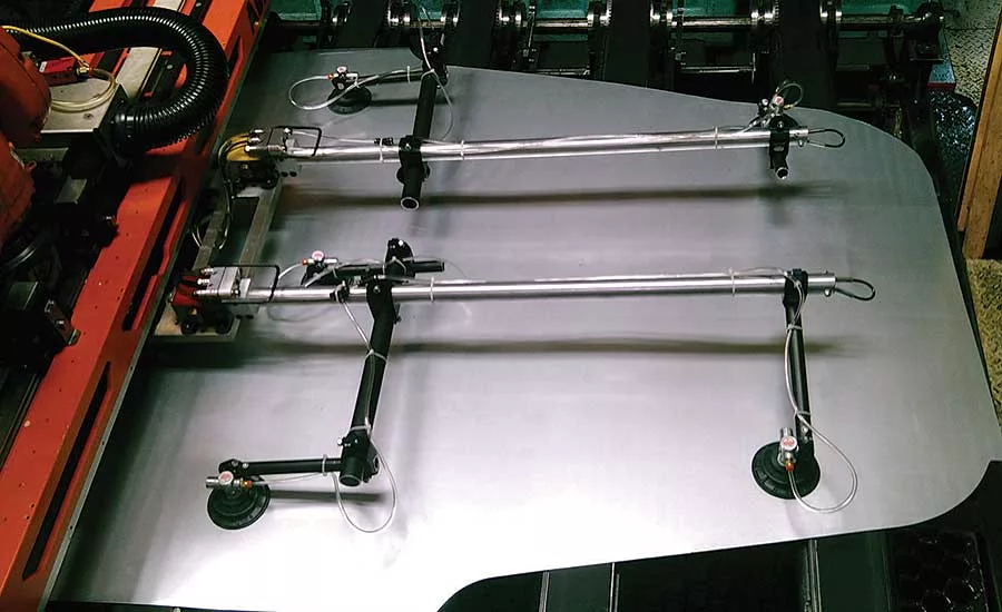
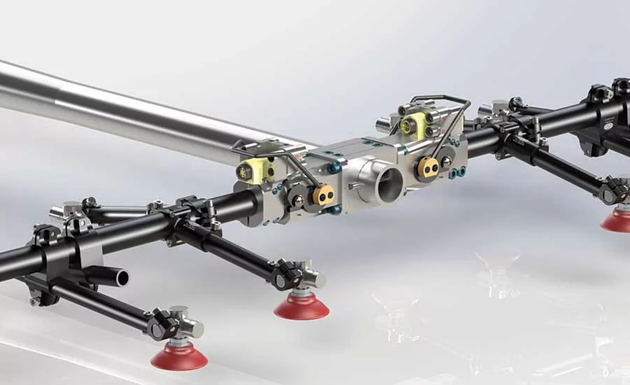
No matter the type of press line is used, keep in mind that stamped parts are not always completed parts. In many instances, the stamping will need to be welded or assembled before it becomes a finished product. In this case, robots and end of arm tooling (EOAT) can play an important role in ensuring the efficiency and accuracy of the metal assembly process. EOAT acts as the robot’s hand, enabling the robot to either hold a part in place or move it to the next station in a manufacturing process.
To maximize efficiency and quality and minimize scrap, this EOAT must be carefully designed and specified. Here are four critical considerations that must be made to optimize robot-dependent press and body shop operations.
Looking for quick answers on assembly and manufacturing topics? Try Ask ASM, our new smart AI search tool. Ask ASM
In The Beginning…
Imagine joining a 100-meter dash from a standing start at the 25-meter mark as all of the other runners are racing past. Or, imagine entering the Indy 500 after the rest of the field has already driven 20 laps. In those conditions, it will be virtually impossible to win the race. Too often, that is the position in which the suppliers of EOAT find themselves.
Engineers typically collaborate with the die maker to create the designs that will be used to form the parts. After several review and revision stages, the die will be approved by the end user and CAD drawings of the dies will be created. At this point, the EOAT supplier will be selected and receive the die data. Using this information, the supplier will create a design and working simulation of the tooling. Upon review of the user, a corrective actions report (CAR) will be written that notes any clearance or clash issues that occurred during the simulation. The CAR will then be sent to the die maker, who will work to resolve those issues before shipping the dies.
To be fair, the reason for this mindset becomes readily apparent when you realize that a fully designed and functional die set can cost upwards of $200,000, while the cost of EOAT will generally be less than 10 percent of that. While it’s understandable that the system designer and end user will devote more attention to the more expensive component, all parts in the system—no matter how big or small, expensive or inexpensive—must work in harmony to create a fully functional and reliable system. If the EOAT supplier is involved earlier in the design process, costly time and rework of the die modifications can be avoided.
Instead, the EOAT supplier is typically merged into the design process upon receipt of a process sheet with suggested grab and grip points where the finger tooling or EOAT will be needed. In trying to catch up, the EOAT supplier will design the system’s touch points, simulate the motions needed (clamp, lift, pitch, unclamp, etc.) and work with the die manufacturer to ensure that the end effectors work harmoniously with the already-produced die.
The die manufacturer will determine if the dies and end effectors are compatible and will be able to deliver what the end user needs. If modifications are needed, a CAR will be created. When all modifications are made, simulations will be performed to see if the system will perform as expected.
Given all of the back and forth between the makers of the dies and the EOAT, it would behoove the end user and system designer to incorporate the EOAT supplier at the outset of the design process. In fact,
thanks to advances in digital-design capabilities and the openness of forward-thinking manufacturers to reconsider the traditional ways of doing things, a “one for all, all for one” mindset regarding robotic EOAT design is beginning to establish a foothold.
Four Things to Consider
Implementing the perfect EOAT system depends on the end user giving due consideration to four critical areas: operating environment, operating parameters, EAOT design, and ancillary components. When these four areas are understood, engineers can make educated choices about EOAT.
Let’s start with the operating environment. There are two environments where robotic part-handling systems are used.
The press shop is where part-stamping processes are performed, though the definition of the press shop has been evolving in recent years. Old-school setups have what is known as a “transfer press” operation, which is a linear operation that relies on non-robotic automation. However, more press shops are incorporating “tandem” lines in their facilities, which use robots to transfer parts from operation to operation. The EOAT in a tandem line must be compatible with the robots.
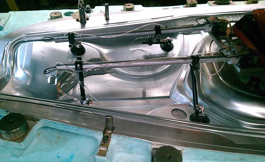
The body shop is the other major location where EOAT is used to move and join metal parts. In the body shop, parts have already been stamped are married together via welding, gluing or fastening. The body shop is a robot-reliant facility, with modular end-effector systems developed to meet the needs of the specific applications, most of which require precise positioning and holding of parts.
Whether the EOAT will be used in a press shop or a body shop, three operating parameters should be assessed and quantified before the best end effector can be selected. They are cycle time, weight and reach.
In the press room, cycle time is measured in strokes per minute (spm), which is the number of parts stamped per minute. For example, a typical transfer press can perform at a rate of 15 to 22 spm. The efficiency of the system design can help improve the spm rate. Advances in digital-design and simulation capabilities can now enable die and end-effector designers to perform interference studies, which can point out potential bottlenecks in the part-moving process. These bottlenecks can then be designed out of the system before it becomes active, which helps optimize cycle time.
The weight of the parts that will be moved plays a huge role in determining the type of end effectors that can be used. It is important that the designer of the EOAT, or transfer fingers, understands that the tooling must be designed as robust and light as possible, so it can perform reliably, with no drops, vibrations or misplacements, and be able to handle thousands of transfer cycles without fatiguing or breaking down.
How far the EOAT will have to extend to perform its required task will also determine which technology is best for the job. It’s best when the robot can reach or travel as much of the required distance as possible. The idea is to limit the amount of offset load or weight of the EOAT or transfer finger. Keeping the EOAT or transfer finger as small and light as possible will help reduce the deflection, resulting in a better automation cadence and more efficient throughput.Once we know the environment and the operating parameters, it’s time to consider how to construct the EOAT.
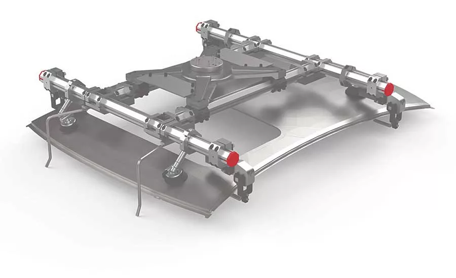
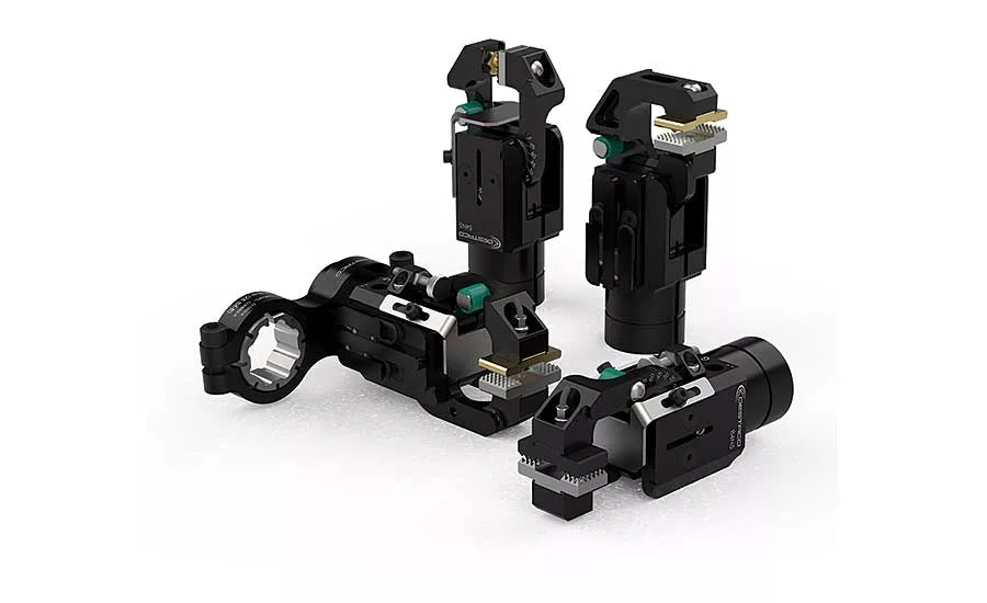
There are two options: modular tooling and welded construction.
Modular tooling is gaining in usage and acceptance. This option requires less design time because the end effector can be built from a standard library of CAD components. This results in better design consistency, along with offering more flexibility if changes in product design are needed. By using a standard design and components, modular tooling requires fewer custom parts, which leads to less assembly time. The finished product will also have less overall weight with reduced startup times and quicker recovery if a crash should occur during operation.
Welded construction brings high levels of durability and reliability. However, it can take longer to design the end effector, since there are fewer standard components available as CAD files. This also makes it more difficult to factor in or predict future design changes, while variations may also exist among design teams. Building a welded end effector can also require more customized parts, which can result in longer assembly times. The end result will be a heavier part and corresponding longer startup times. Crash recovery can also be longer with a welded part.
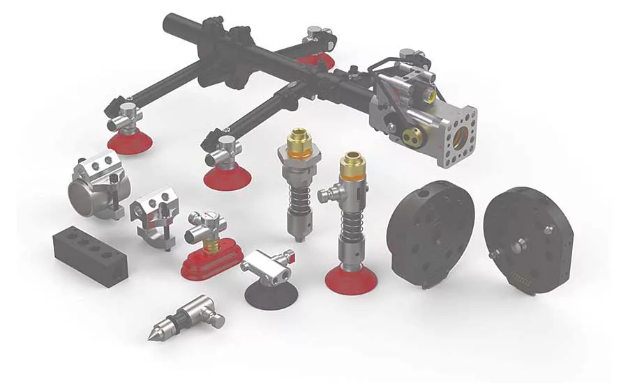
The last thing to consider are the ancillary components that can be used with the EOAT. These include vacuum cups, magnets, venturis, grippers and clamps.
Vacuum cups and magnets actually contact the part or finished product that needs to be held or moved. Vacuum cups are most popular for this task and are available in a variety of vacuum sources, sizes, shapes, treads, flexibility levels and materials. They are typically made from rubber, though polyurethane is making some headway in the market. Magnets are used in applications where there is insufficient surface area to reliably and safely pick and place the part with vacuum cups.
Venturis have gained acceptance as the main source of supplying vacuum to vacuum cups. Traditional systems operate with two lines, one that creates the vacuum, which allows the retrieval of parts, and a second that adds air to the cup, which allows the part to drop. However, new single-line venturis are gaining in popularity. Single-line venturis require 50 percent less air, which reduces operating costs. With only one air line that needs to be serviced, maintenance costs are also reduced.
Sheet-metal grippers or power clamps can be used to hold the parts during forming or welding. Lightweight sheet-metal grippers are ideal for use in part-handling applications in a press shop. The gripper’s internal mechanism prevents it from opening when air pressure is lost. Sheet-metal grippers come in an array of grip styles with multiple contact-point options. When part handling in the body shop, power clamps are often used. They feature an enclosed pneumatic toggle-lock. Power clamps with integrated open-close sensing can secure a part even when air pressure is lost.
Looking for a reprint of this article?
From high-res PDFs to custom plaques, order your copy today!


