Understanding Line-Scan Cameras
Line-scan cameras excel at producing images of objects in continuous motion past a fixed point.

Compared to manual inspection, vision systems deploying area-scan cameras offer improved accuracy and far higher consistency. Plus, they work nonstop without suffering fatigue or requiring a paycheck. For all their advantages, however, there are limitations to area-scan cameras in more challenging machine vision tasks. For example, if the object under inspection is large, if it is continuously moving, or if the task requires high resolution without blurring, a line-scan camera is a far better choice.
Area-scan cameras have a square or rectangular sensor that captures an image all in one go. The resulting image has a width and height corresponding to the number of pixels on the sensor. Because of this, area-scan cameras are ideal for many machine vision tasks, where the objects are small and having almost the same size in both dimensions. However, the size of PCBs, LCD panels and wafers has increased beyond the speed, accuracy, and resolution capabilities of area-scan cameras, making line-scan cameras a better choice for inspecting these objects.
There are key differences between area-scan and line-scan cameras. The most important is how an image is acquired. Unlike an area-scan camera that captures the entire object in one 4:3 frame, a line-scan camera uses a single row of light-sensitive pixels that image across the object, line-by-line, accompanied by high-intensity lighting. A completed image is built by stitching together the lines, much like a fax machine.
Here is how it works: Each pixel accumulates photoelectric charges relative to the light from the object imaged onto that pixel. Next, a readout register amplifies, adjusts and digitizes the charges, all while the next row of pixels is being exposed. The time between exposure and readout is the “line rate,” calculated in kilohertz (kHz). To avoid under- or over-sampling an object, a programmable encoder connected to, say, a conveyor or web, measures speed and precisely synchronizes the camera in pulses. Each line of the image is then stitched together in a predetermined number to form a frame for analyzing with software. Any defects found are recorded on roll maps.
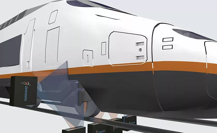
Because of this design, line-scan cameras excel at producing a flat image of cylindrical objects, imaging large objects with high resolution, or producing images of objects in continuous movement past a fixed point, such as parts on an assembly line or web applications. Line-scan inspection applications are wide and varied including paper, rolls of metal, fiber, railway inspection, solar cells, textiles, pharmaceuticals, semiconductors and postal sorting. Plus, the cameras can fit into tight spaces, for example when it must see through rollers on a conveyor to acquire images of the bottom of a part.
Like most advanced technology, line-scan cameras are constantly improving in performance while becoming more affordable. Manufacturers are producing cameras with increasingly smaller pixels and higher line rates to detect increasingly smaller surface error sizes of PCBs and liquid-crystal displays, among others.
Color Inspection
For many years line-scan cameras have been deployed in color inspection, a trend mainly driven by the needs of the printing industry. There are three types of line-scan cameras for color imaging applications: bilinear, trilinear and three-chip. The trilinear approach, which uses three linear arrays—red, green and blue (RGB) channels—fabricated on a silicon die, has gained support from imaging professionals because it captures details with outstanding color fidelity. Trilinear cameras also have a smaller footprint than bilinear cameras, and they reduce system-level costs because they use standard lenses. In contrast, bilinear cameras have less resolution, despite having the same number of pixels. Also, bilinear color information must be interpolated, since not every pixel is imaged in all three colors.
Looking for quick answers on assembly and manufacturing topics? Try Ask ASM, our new smart AI search tool. Ask ASM
The trilinear approach calls for each of the three arrays to capture one primary color (RGB) simultaneously, but at somewhat different locations on a moving object. To form a full color image the three color channels are combined. To compensate for the separation, referred to as spatial correction, the first and second arrays are buffered to match with the third. The downside of using only three channels is relatively low spectral resolution. Manufacturers have improved performance with image-based color measuring approaches that enable color to be measured on the whole surface of the object and not only on one spot—as it is with traditional spectrophotometers.
For truly accurate color inspection, this approach is needed, and for that, line-scan cameras with more than three color channels are required. In general, increasing color channels reduces the resolution of area-scan cameras. However, line-scan cameras still provide high spatial resolution despite adding high spectral resolution by use of more color channels. Modern multispectral line-scan cameras feature six to 12 spectral channels and stay in the 360 to 960 nanometer wavelength range for these applications. The innovative multichannel imaging technology provides accurate spectral and color output on varying substrates such as paper, plastics films and foils.
Precise color information based on images requires not only more color channels, but also homogeneous illumination and special software for color calibration and color calculation.
It should be noted that in certain applications, color imaging is no longer enough, such as in currency inspection, electronics manufacturing and food sorting, where specific wavelengths are required that are either outside the visible spectrum or in between the RGB color bands. Multispectral imaging can be used to inspect in the near infrared range, as well, up to 960 nanometers.
3D Line-Scan Inspection
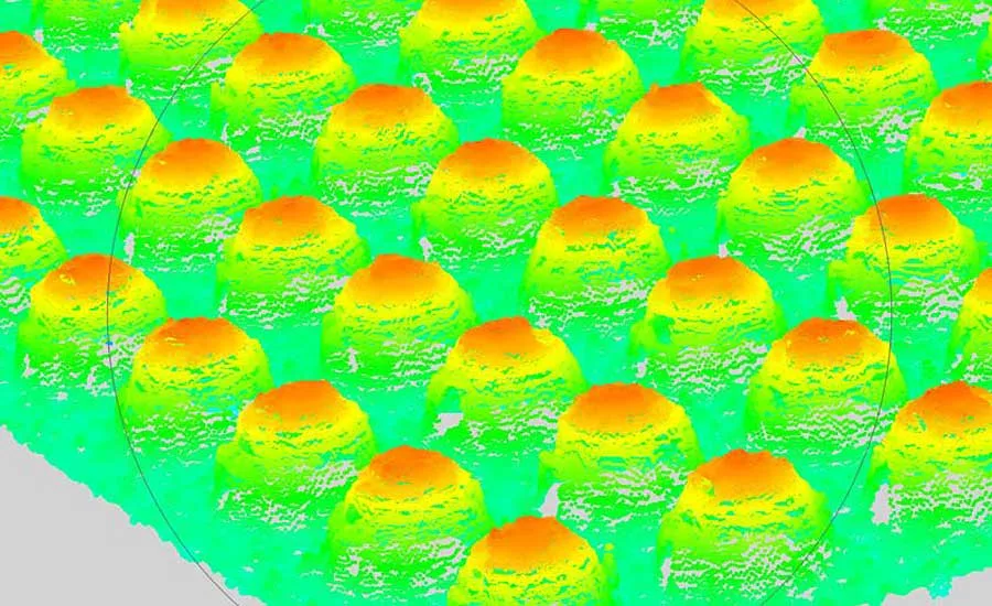
Over the past few years, vision system manufacturers have introduced a variety of 3D imaging methodologies, ranging from time-of-flight analysis and projected pattern correlation to laser triangulation measurements and stereoscopic technologies. Of these, stereoscopic, or just “stereo,” systems have gained the most traction, particularly in the semiconductor industry. Components, such as solder balls or pins used to connect wafers and dies, must be inspected with 3D methods to precisely measure the height of the conducting elements. The typical dimensions of such components are around 50 microns, which means the inspection system must have optical resolution of at least 5 microns.
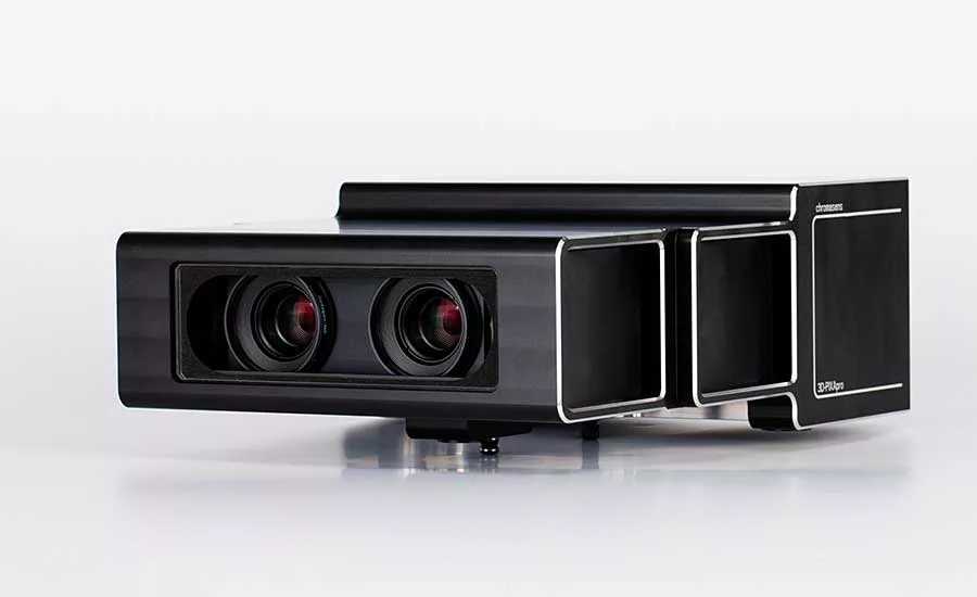
The basic concept behind stereo 3D vision systems resembles that of human vision. Two image sensors in a stereo configuration are combined into one camera, resulting in two images being acquired of the same object from slightly different perspectives. This serves as the basis for triangulation, which involves an object point projected in both stereo images, and two image points that are the positions of the right and left cameras.
Vision system suppliers are now combining the best of both worlds: line-scan with stereo. These cameras have linear sensors up to 8,000 pixels in RGB to provide both high resolution and a large field of view. Fine structures on the surface of the object under inspection are resolved using high-resolution images, which is an advantage for the passive stereo approach. Because of this improved accuracy, they open up new 3D applications that are not possible with other approaches to detect the most minute of defects. Another advantage is speed. Linear sensors have line rates of up to 50 kHz even at extremely high resolutions. Finally, this approach results in less occlusions: The stereo line-scan cameras are oriented perpendicular to the object surface, and there are no occlusions in transport direction.
Light is important to all line-scan operations, but it is crucial with 3D. For high speed, the camera’s line rate must increase, resulting in the available exposure time being decreased, and requiring system developers to increase illumination intensity. When selecting the correct lighting for line-scan camera applications, the following factors should be considered:
- The lens aperture and the light amount significantly influence the signal noise ratio. Higher light intensities reduce noise level.
- LED systems offer definite advantages compared with traditional lighting technologies, such as halogen or fluorescent lamp.
- Good cooling ensures long durability, consistent spectral behavior and a high level of brightness homogeneity and intensity over the whole field of view.
- Color, ultraviolet and infrared LEDs are versatile, providing for more flexibility in system design.
- The use of polarizing filters prevents unwanted light reflection on shiny surfaces.
New reflector technology is now available that assures optimal homogeneity and intensity for lighting even from different distances. Elliptical reflectors, instead of lenses, focus the LEDs so that color aberration is eliminated, greater efficiency is achieved and high power can be delivered at longer working distances. Light characteristics influence how the image looks like: a dark field illumination results in a complete different image compared with a dome like illumination. This is important for the passive stereo approach.
For more information on line-scan cameras, visit www.chromasens.com.
Looking for a reprint of this article?
From high-res PDFs to custom plaques, order your copy today!


