Spin Welding for Plastics Assembly
Enhanced data gathering and automation features complement spin welding’s ability to join plastic parts with a round-to-round interface.
Management theory and practice don’t always match, and few people know this better than the individuals who oversee assembly lines. Their real-world experience has taught them that the best method to achieve success always depends on several application-specific factors. Among them are part size and shape, available automation, required cycle time and the materials being joined.
Plastic parts, for example, can be assembled using various welding techniques. But, when the part is made of a semi-crystalline material and has a complex geometry with a circular joint interface, spin welding, a type of friction welding, is the method of choice.
“Ultrasonic welding is great for welding plastic parts, but it’s better to use spin welding when the parts are made of a semi-crystalline material like polypropylene,” explains Eric Kuzniar, senior project engineer for assembly and welding at Emerson. “The reason is because polypropylene polymers solidify abruptly and don’t ultrasonically transfer energy very well, thereby limiting its effectiveness.”
This unique capability of spin welding accounts for its wide use in packaging, as well as the assembly of plastic insulated cups, filters, filter housings, fittings to housings, caps to housings and conjoined pipes. Kuzniar says such items are frequently used in refrigerators, faucets, industrial equipment, combustion engines and medical devices.
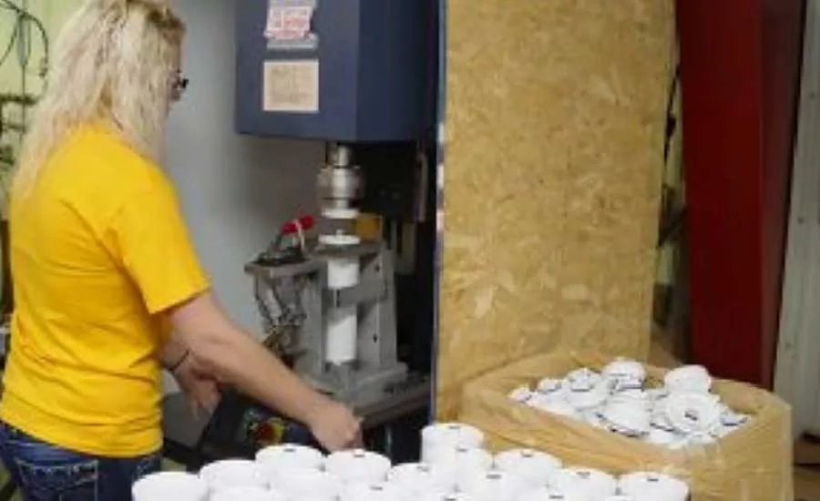
For the past several years, Garnavillo, IA-based Guttenberg Industries Inc. has been molding top and bottom filter canister sections and spin welding them for a medical device company. Engineers at Guttenburg initially planned to use electromagnetic welding, but switched to spin welding (using a Dukane SVB machine) when the technology proved to be capable of welding assemblies at twice the production speed of the molding machine. Each finished canister is also leak-tested to withstand up to 350 psi water pressure.
Originally developed in the 1960s to join metal parts, spin welding has been used for thermoplastics assembly since the 1970s and has grown increasingly popular since then. Heck, Mattel Inc. even sold Spinwelder kits in the mid-1970s that let youngsters use a battery-powered hand tool to weld multi-plastic-component cars, planes and helicopters.
At the industrial level, spin welding technology for plastics assembly has made great strides in recent years. Long gone is the need to use a drill press to rotate one part against another. Manufacturers now use state-of-the-art machines with servomotors and sensors that provide full control over speed, acceleration and deceleration, and weld and hold time to consistently produce high-quality parts with super-strong welds.
Looking for quick answers on assembly and manufacturing topics? Try Ask ASM, our new smart AI search tool. Ask ASM
Rotation Under Pressure
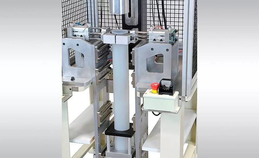
Spin welders come in tabletop and inline versions. The former type looks quite similar to an ultrasonic welder, with a vertically mounted linear actuator (pneumatic cylinder or servo-driven ballscrew) perpendicular to the tooling base. The latter is recommended for more difficult or exacting applications.
As for the parts to be welded, one is rotated on the drive head (mounted to the end of the ram) and the other is kept stationary. On inertia-type welders, the drive head is powered by an air motor and flywheel. Continuous-drive welders feature either a direct-drive electric motor with dynamic braking or a servomotor.
Spin welding often requires a means by which the welder grips the spinning part. If the part is large, ribs or a toothed surface can mate with the driving fixture. With smaller parts, friction alone may do the trick.
At the start of the cycle, the motor begins rotating the head. When its target speed is reached, the head descends and the parts are pressed together. The resulting friction generates enough heat to melt the plastic.
In the molten state, material from each part mixes together at the interface and forms a weld. Pressure is then maintained on the parts for a short time to allow the plastic to solidify. The overall cycle time is 2 to 6 seconds, says Kuzniar, not counting the time to load and unload parts.
“With an inertia welder, friction between the plastic components acts as the brake that stops the flywheel,” explains Mark Iannantuoni, northeast regional sales manager at Dukane. “Machines with an electric motor use a separate brake to stop the drive head, whereas machines with a servomotor use its ability to accurately stop at a fixed radial orientation.”
One of the advantages of using an electric-motor-powered head is versatility. Besides contacting the top part before rotation begins, the head can come down, retrieve the part, rise up, begin spinning and then come back down again to make the weld. Alternatively, it can contact the top part and then begin spinning.
A servomotor provides the most control over the drive head, notes Iannantuoni. It can trigger the head to start spinning once the parts touch, weld to a specific collapse distance and even stop the part at a specific point during welding.
Dukane equips its Servo Weld Plus spin welder with two servomotors—one for the drive head and another for the Z axis—to consistently ensure accurate angular orientation and overall assembly height. In addition, the Melt-Match mode coordinates the motion of the Z and spin axes during welding so they match the melt rate of material being welded.
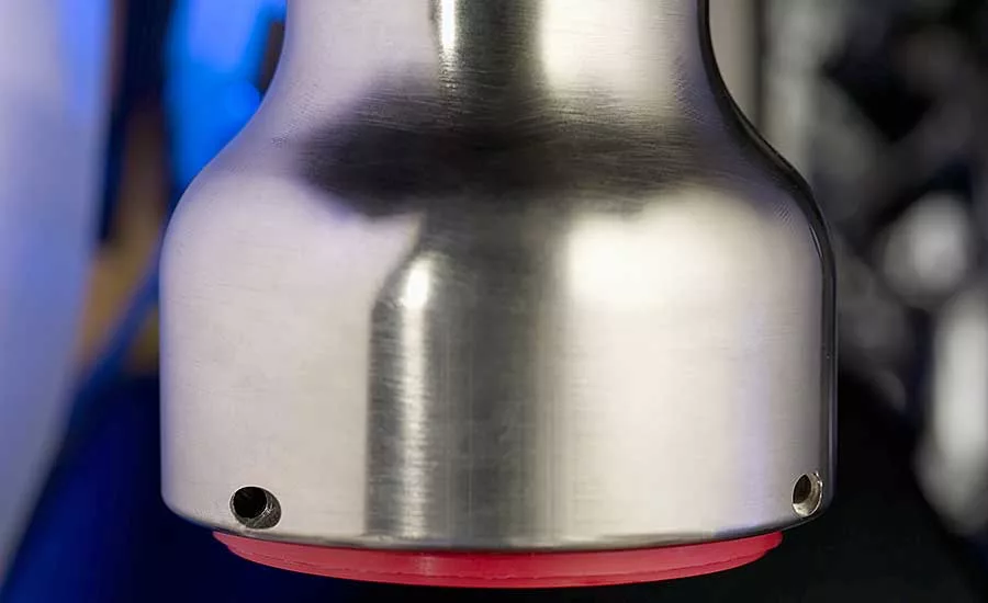
Since 2015, a large medical device manufacturer has used the Servo Weld Plus to join polycarbonate plastic caps to the end of hollow, stainless steel tubes. The biggest challenge for the company, according to Iannantuoni, is making sure the cap exactly aligns to the tube end, which has tiny knurls on it.
“The tube is 18 inches long, but the welding interface is only about 0.002 inch,” explains Iannantuoni. “After learning about our dual servo welder, the company came to us hoping the machine would be able to exactly align the height of each part. For the past eight years, the machine has continuously performed as needed for high-production welding of quality parts.”
The use of spin welding to join plastic to metal parts is rare, acknowledges Iannantuoni. Its level of success greatly depends on using metal with ions that plastic can thoroughly melt into and strongly bond with. Some eyeglass manufacturers use spin welding to join metal hinges to plastic frames.
Theoretically, there is no size limit to the parts that can be joined by spin welding. Parts with walls as thin as 0.4 millimeter, and as thick as 10 millimeters, can be welded using this method. Similar to ultrasonics, several joint designs are available to create a hermetic seal. These include tongue-and-groove configurations, shear joints and scarf joints.
Because many applications require a precise final orientation of the parts, it is a good practice to add small tabs that should align when the welding cycle is complete. This greatly simplifies weld setup and inspection; operators know that if the two tabs line up, the part is in the correct orientation.
As for the limitations of spin welding, all parts need to have a round-to-round interface and be flat. The process also produces more flash and particulate matter than ultrasonic welding, but, flash traps can be used to create more aesthetically pleasing welds.
A common in-process challenge, especially with inertia welders, is controlling the final orientation of the two parts after the weld is set. Servomotor-driven models offer the most control, but cost about three times more than inertia spin welders.
Happy Customers
Like any welding technology, spin welding has its market niche. Tier 1 automotive suppliers and manufacturers of filters and filter housings remain the biggest users of the process.
Spin-welded automotive parts include durable under-hood parts like small elbows on manifolds, valves, tanks and bottles. Another application is welding extruded tubing to molded attachments for fuel filter lines.
Nonautomotive parts include plumbing floats, paint can lids, and tumblers, wherein the inner liner is welded to the outer body. One of the hottest growth areas for spin welding, according to Iannantuoni, is assembling circular thermoplastic housings that surround batteries used in hybrid and electric vehicles.
White goods manufacturers rely on spin welding to assemble vacuum cleaner housings and flow diverters. In the medical field, fluid recovery and other devices are often spin welded, although particulate generation does somewhat limit the process’ appeal in this market when compared with ultrasonic welding.
“The best plastic assembly applications for spin welding are those where both parts are chemically compatible and melt at about the same temperature,” notes Dan Schewe, regional sales manager at Forward Technology. “Equally important are those applications where spin welding offers a safer, easier method of assembly.”
Examples of these applications, according to Schewe, are those where toxic glue is used or extra hardware like a hose clamp is required to hold the two parts together. Not using toxic glue enhances worker safety, and eliminates the need for vent hoods to exhaust fumes, and staging parts during curing.
Schewe says that removing a clamp from an assembly process not only takes away the need for expensive torque-driving equipment to tighten the clamp. It also eliminates the need for associated equipment and fixturing needed to align the parts before clamp tightening.
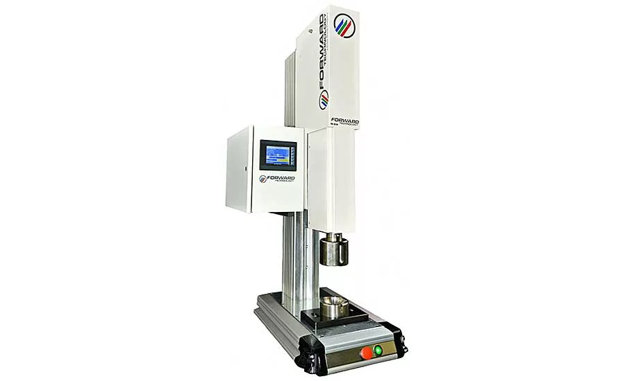
Forward Technology makes three spin welding machines: the basic PSW (with a pneumatic press and motor for spin function), the mid-level HD-OSW (a pneumatic press with fully programmable servo motor for spin function), and the top-level HD2X-OSW, which offers programmable servo press actuation and a servomotor for spin function. Schewe notes that the HD-OSW welder is the company’s biggest seller.
“The mid-line welder lends itself to 90 percent of the spin welding applications that cross our desks because it provides fast, powerful performance on a range of polymer materials and part diameters,” explains Schewe. “It features modes that allow welding by time, height, travel, and finished-part orientation. Plus, it easily integrates into automation, and has the ability to be controlled and share weld data via an Ethernet connection.”
A Technology for Today
“End-users of spin welders want different things today than they did back in the 1990s,” says Kuzniar, who has more than 25 years of experience with the technology. “Then, the focus was primarily on creating a strong weld, even if it required constant monitoring and mechanical apparatuses to improve control. Today, customers want extensive data on each weld for traceability, as well as advanced automation features that enable communication with the local PLC for optimum process control and repeatability.”
The Branson SW300 is a servo-driven spin welding system that can be configured for manual, semiautomatic, or fully automated manufacturing applications. Its servomotor accuracy is ±0.1 degree, and there is a mechanical stop indicator on the outside of the actuator.
A standard Ethernet port on the machine allows for live last-cycle data transfer between the welder and a remote PC. A cable connection allows for communication between the welder and automation/PLC using I/O.
“Weld data information for up to 15 previous cycles is available to the operator on the interface,” says Kuzniar. “This data, which is user selectable up to 250 previous cycles and can be output to a PC via a USB stick, includes recipe name, mode, spin direction, pre-weld and peak weld speed, number of revolutions, final orientation, absolute position, peak torque, collapse distance, trigger mode and setpoint, cycle count, and dwell, hold, cycle and weld time.”
One manufacturer of consumer packaged goods has used the SW300 for several years to create an air and watertight seal between the upper “capsule” portion of a cap (containing an additive powder) and the cap’s screw-on base. This design lets the user puncture the seal and directly release the additive into the water before drinking.
“The customer’s initial efforts to seal the reservoir portion to the base were ineffective,” recalls Kuzniar. “The seal leaked, allowing moisture to absorbed into the powder, which damaged its integrity prior to the user puncturing the cap’s base.”
Emerson’s engineers worked closely with the end-user to design a custom tool that uses a knurl to grip the low-density polyethylene parts and prevent slippage during spin welding. The team also developed a prototype fixture and a custom software program to ensure the creation of a clean hermetic seal at the joint to optimize the welder’s overall cycle.
“Spin welder sales have remained steady the past few years, but customers increasingly want welders that produce strong welds on a repeatable basis,” notes Iannantuoni. “Some manufacturers are also designing the radial areas of parts with more stringent requirements. These trends are the result of a desire to remove inconsistency from the process, and the reason for the increasing popularity of servomotor-based machines.”
“From my prospective, there seems to be no noticeable rise or decline with the use of spin welding,” says Schewe. “However, there is a paradigm shift within manufacturing towards more efficiency and automation, partly due to the labor shortage. This is changing how we package some of our spin welders.”
He adds that manufacturers want to collect and store process settings and weld data. Such data enables the end-user to track unauthorized or undesired changes to a machine program, schedule preventative maintenance, and maintain part quality and traceability.
Sonics & Materials Inc. makes two high-torque spin welding machines that can join a wide range of spherical and cylindrical parts. Both models are PLC-controlled and can be used as stand-alone welders or integrated with automated inline assembly systems. They come standard with a power head on dual columns, a multi-hp electric motor drive and dynamic braking.
Model 1010 has a fixed vertical opening with a 10-inch space. The opening on Model 1020 is adjustable from 10 to 20 inches.
Regardless of the application, engineers are well-advised to contact welding equipment suppliers as early in the design process as possible—preferably before any molds are cut. This collaborative approach can help manufacturers work through any design constraints and create the ideal joint design.
Looking for a reprint of this article?
From high-res PDFs to custom plaques, order your copy today!


