How to Speed Up EV Cable Assembly
Automation can improve wire processing quality and throughput.
Loading the ferrule onto the cable is critical, but it can be done manually. Photo courtesy Schleuniger Inc.
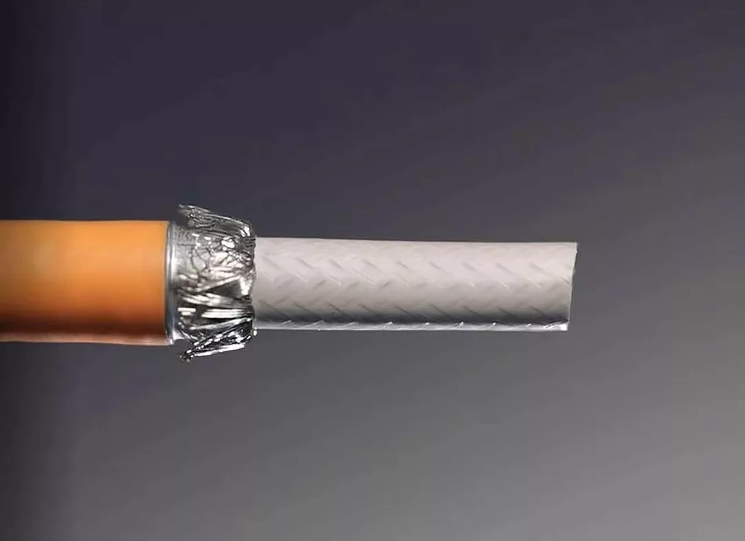
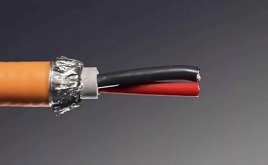
If the cable has a foil layer, it must be stripped cleanly, flush with the outer jacket. Photo courtesy Schleuniger Inc.
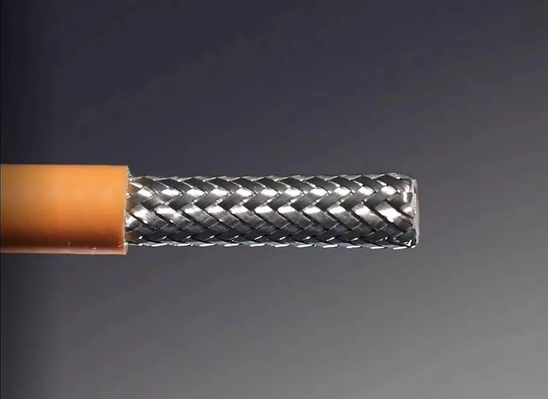
Different connectors require different fold angles to ensure the connector fits together properly. Photo courtesy Schleuniger Inc.
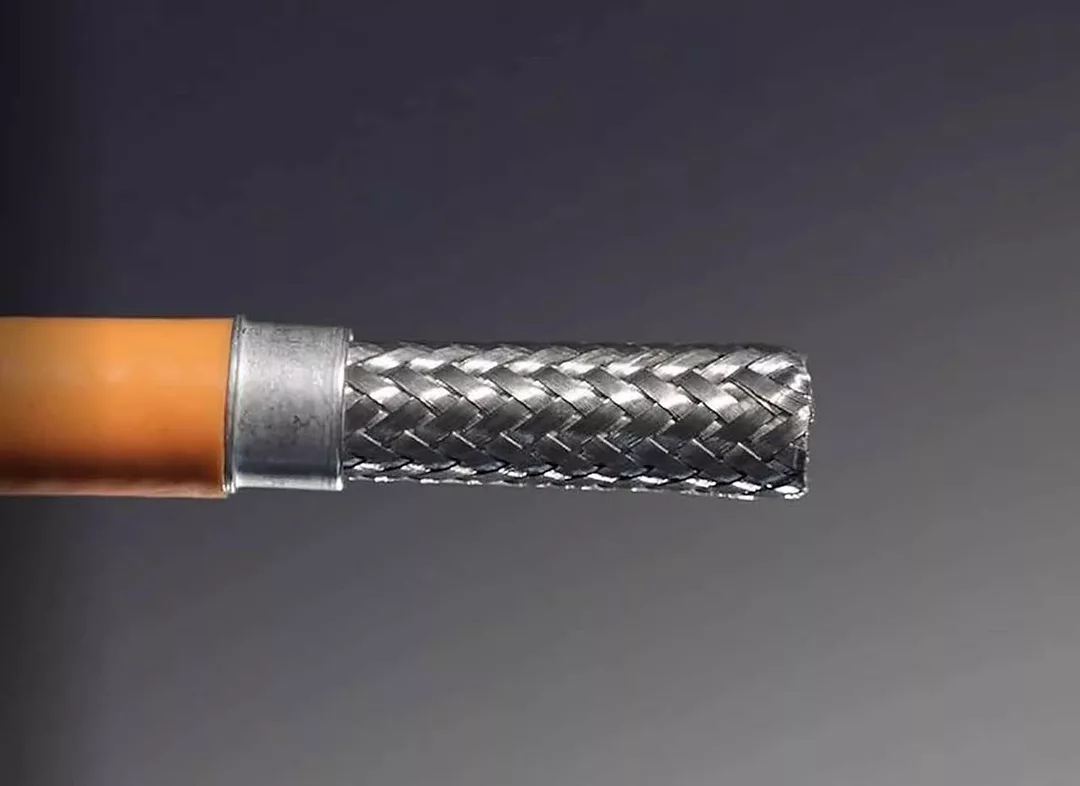
Properly cutting the shield consistently with a traditional rotary stripping unit is very challenging for high-voltage cables. Photo courtesy Schleuniger Inc
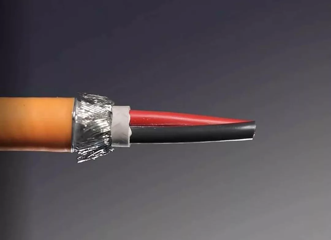
The dielectric or filler can be removed in the same way as the outer jacket. Photo courtesy Schleuniger Inc.
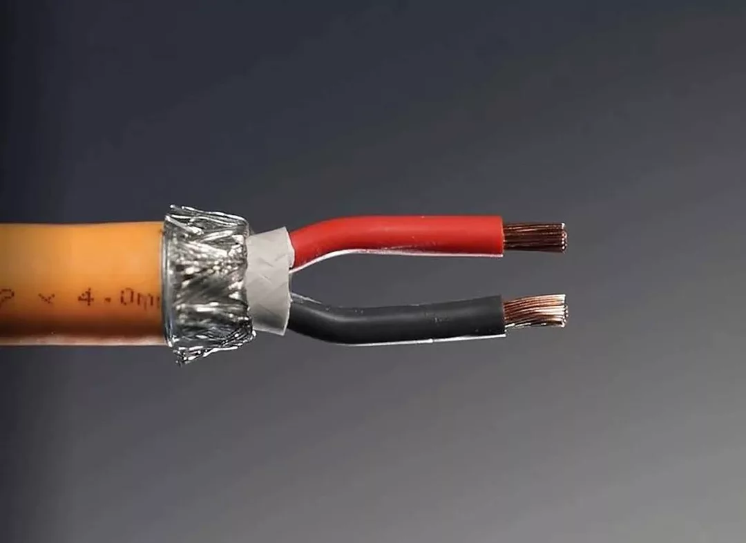
Prior to terminating multiconductor cables, the cable must be oriented properly so that polarity is correct when the conductors are plugged into the connector. Photo courtesy Schleuniger Inc.
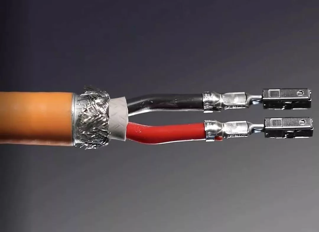
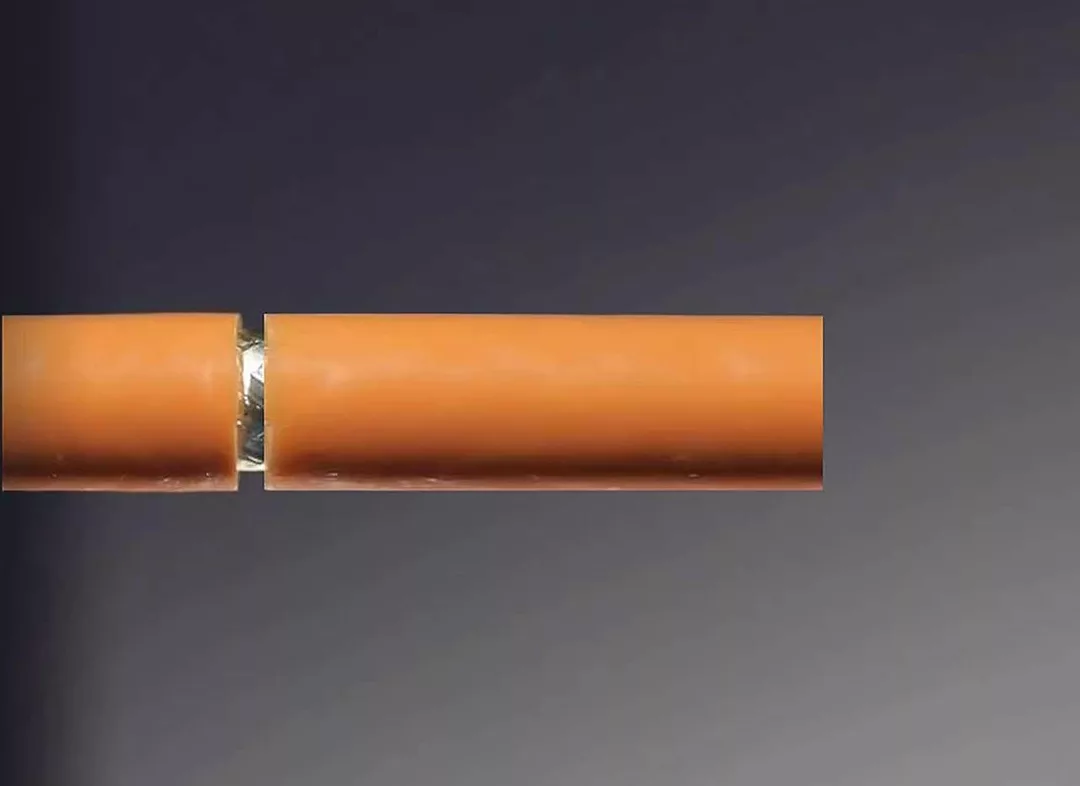
Inner conductors are either crimped or ultrasonically welded to the terminals. Photo courtesy Schleuniger Inc.
Wire ends and terminal positioning must be consistent. Photo courtesy Schleuniger Inc.
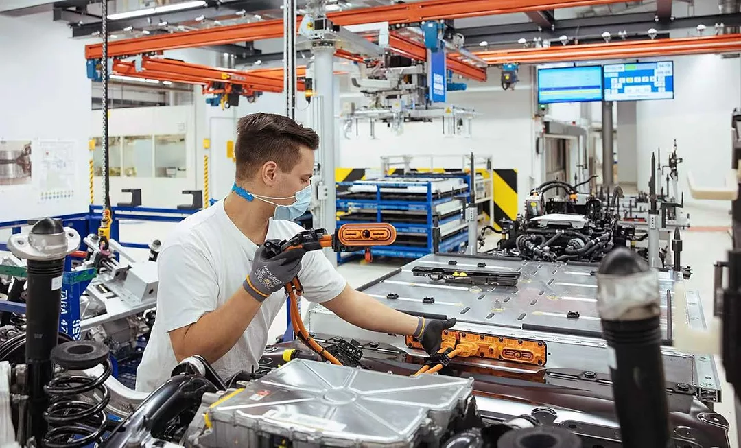
Electric vehicle cable harnesses are a hot topic in the wire processing industry today. Photo courtesy Volkwagen Group
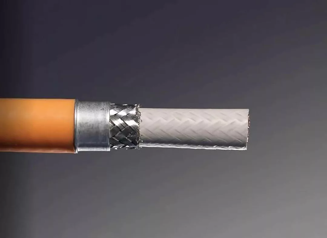
Cables without a foil layer around the shield are easier and faster to strip. Photo courtesy Schleuniger Inc.
Electric vehicle cable harnesses are a hot topic in the wire processing industry today. It’s an exciting market that’s changing rapidly as new techologies emerge.
High-voltage connectors used in EV harness applications have many components that require precise assembly. Automation can improve productivity, quality and throughput when stripping and crimping cables.
High-voltage connectors require several production steps that must be performed in a specific sequence. While most engineers want to automate every process, the cost of a fully automatic system cannot always be justified.
Some process steps are more challenging and require more precision. For instance, removing the foil layer or cutting the shield is critical, because connector performance or safety may be affected significantly. In addition, some process steps are required for almost all connectors and cable types, while other steps are required only for certain connectors.
Depending on the volume of a particular connector series, it might make more sense to automate only the critical steps and continue the simpler or uncommon steps with manual processes. However, everything can be automated, if production volumes justify it.
Currently, more than 97 percent of high-voltage applications require shielded cables—either multiconductor or coaxial cables. Applications range from 3 square millimeters up to 120 square millimeters in single-conductor (coaxial) or 2 by 2.5 square millimeters up to 5 by 6 square millimeters in multiconductor cables for a variety of single- and multi-cable connectors.
To achieve precision and throughput, manufacturers must invest in automation. It can provide not only high precision, but complete flexibility so that processing requirements can change in the future. It is important that systems can be expanded so they can grow and adapt as demand changes.
Looking for quick answers on assembly and manufacturing topics? Try Ask ASM, our new smart AI search tool. Ask ASM
Different connectors often have very different individual process steps because of their unique functions and constructions. However, there are some basic steps that apply to almost all of them. These steps pertain to properly stripping the cable and loading the ferrules.
Remove Outer Jacket and Foil
Cables without a foil layer around the shield are easier and faster to strip. These cables can be stripped with radiused fixed blades, rotary stripping blades or a laser stripper.
Radiused fixed blades will likely be the fastest, but perhaps not the safest, for quality. If one blade is sharper than the other, the blades will not penetrate the insulation evenly and may damage the shield. If the cable is not very concentric, it is nearly impossible not to damage the shield. Changing to a different cable size requires a blade size change as well.
Laser stripping is popular. There is no way to damage the shield, because the laser beam is reflected off of the shield. However, if the shield is not woven tightly, the laser can penetrate the shield and damage the inner layers. Laser strippers require fume extraction, since some fumes are toxic. They are also the most expensive, compared to other stripping methods.
Rotary stripping will provide the cleanest cut using blades and conductor detection systems that can prevent damage to the shield. Special processes can be used for nonconcentric cables.
When the outer jacket is molded into the shield, it’s more difficult to remove the jacket without disturbing the shield. For these cases, manipulating the slug in certain directions while pulling it off of the cable helps the slug break away from the shield.
If the cable has a foil layer, it must be stripped cleanly, flush with the outer jacket with no flags remaining. This is nearly impossible with fixed blades. It is certainly possible with a laser system, unless the foil is bonded to the outer jacket. Laser systems require space for the laser to get to the foil.
However, if the foil is bonded to the outer jacket, any pulling of the slug may cause the foil to tear unevenly. Lasers will also not cut where the foil overlaps.
With rotary stripping blades, it’s possible to score the foil without pulling the slug. The jacket slug and foil can be removed simultaneously by manipulating the cable and twisting the slug as it is removed. The result is a clean foil cut that is flush with the outer jacket.
Assembling the Inner Ferrule
Loading the ferrule onto the cable is critical, but not overly challenging if done manually. However, different connectors use different ferrules. Therefore, it should be possible to change over to different ferrules with a few cable- and ferrule-specific parts. The system should also have the ability to detect if the ferrule is the correct type and if it is properly oriented on the cable.
Installing the ferrule onto the cable is a step that could be done manually to save costs, since automatic loading systems are quite expensive.
Cutting and Removing the Shield
Properly cutting the shield consistently with a traditional rotary stripping unit is very challenging for high-voltage cables, especially if the cable has nonconcentric layers or is otherwise out-of-round. The integrity of the dielectric and filler are critical for proper performance of the cable. Traditional rotary stripping machines risk damaging the inner layers.
An anvil and punch system guarantees the inner layers will not be damaged and cuts the shield cleanly and evenly, 360 degrees around the cable.
The resulting shield length will depend upon the ferrule being used, since it will be wrapped around it. The cut must be clean and consistent. Otherwise, long strands may cause shorts with other components and short strands may degrade the integrity of the ferrule crimp.
Sometimes, the shield length is longer than the length of the dielectric. These applications require the shield to be opened and folded back after it’s trimmed so that the inner layers can be stripped.
Fold Shield
The shield gets folded back over the ferrule, but in some cases, not completely. Different connectors require different fold angles to ensure the connector fits together correctly. The fold angle may be between 90 to 180 degrees, but the fold must be even, 360 degrees around the ferrule.
The shield strand ends should fall within the specified tolerances to ensure proper performance. Strands that are too long may cause shorts and short strands might not secure the shield properly when the outer ferrule is crimped.
Removing Dielectric or Filler
The dielectric or filler can be removed in the same way as the outer jacket. Multiconductor cables are not allowed to have any damage to the conductor insulation.
For coaxial cables, conductor detection can play a big role in ensuring the center conductor is not damaged by the stripping blades. As with the outer jacket, the system must be able to accommodate nonconcentric cables to provide the most flexibility.
Prior to terminating multiconductor cables, the cable must be oriented properly so that polarity is correct when the conductors are plugged into the connector. Photo courtesy Schleuniger Inc.
Multiconductor Orientation and Stripping
Prior to terminating multiconductor cables, the cable must be oriented properly so that polarity is correct when the conductors are plugged into the connector. Sophisticated systems must be able to recognize the wire colors and then rotate the cable accordingly without losing cable position.
Once oriented properly, the conductors are formed to enable termination according to the connector cavity pitch. After the conductors are properly formed, the ends should be stripped on a device with conductor detection to ensure the wire strands are not damaged.
Termination
Inner conductors are either crimped or ultrasonically welded to the terminals. Automation systems can integrate suitable crimping presses with crimp force monitoring systems. Ultrasonic welding systems typically have integrated monitoring to ensure a proper weld.
Automation systems that can integrate third-party systems are very convenient. They can minimize the validation process for presses and welding systems that have already gone through lengthy approval processes.
Multiconductor Connector Loading
For multiconductor cables that will be terminated and loaded into a connector, it’s critical that the wire ends and terminal positioning are consistent. This will ensure that the terminals will load and lock into the connectors properly.
Subsequent housings or components can be applied automatically and locked into position, if volumes justify it. Automating these process steps will likely give you the best return on investment since they are most commonly applied.
New visual inspection systems can inspect 360 degrees around the cable. Artificial intelligence is utilized to identify the different layers of the assembly to perform a thorough analysis. And, numerous quality characteristics can be programmed for each assembly.
When inquiring about an automatic high-voltage cable connector system, engineers should be prepared with the following information:
- Cable specifications and stripping requirements.
- Connector specifications and the necessary process steps.
- Quality assurance requirements.
- Production requirements and required cycle times.
Considering how fast EV technology is evolving, automation systems should be flexible and adaptable, without causing major interruptions in production. For instance, it should be possible to move semiautomatic stations onto a fully automatic platform. Similarly, a fully automatic platform should be expandable as production volumes increase over time. This feature will give you the most flexibility and enable you to leverage your investment moving forward.
Looking for a reprint of this article?
From high-res PDFs to custom plaques, order your copy today!


