Autonomous Mobile Manipulators for Aerospace Assembly
A new approach for assembling composite aerostructures uses autonomous mobile robots and lightweight assembly jigs that compensate for deformation.
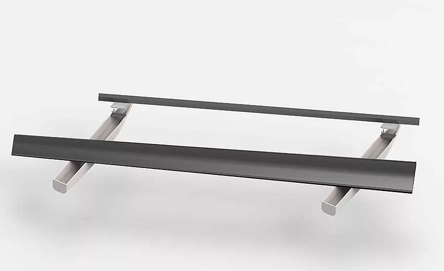
This rendering shows the flap with supports and a mock-up of the airplane’s rear spar. Photo courtesy Braunschweig Technical University
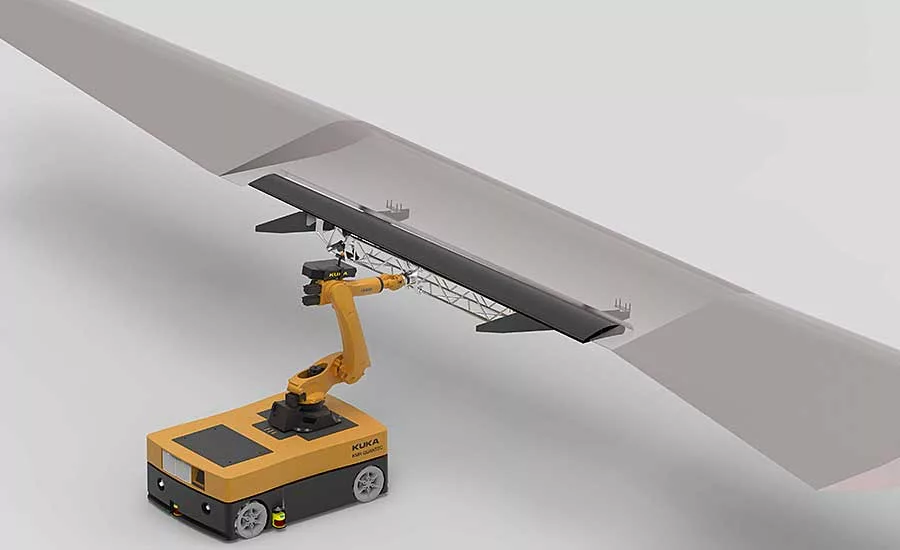
The researchers developed a unique approach for assembling wing flaps using an AMR and a lightweight assembly jig that compensates for deformation. Photo courtesy Braunschweig Technical University
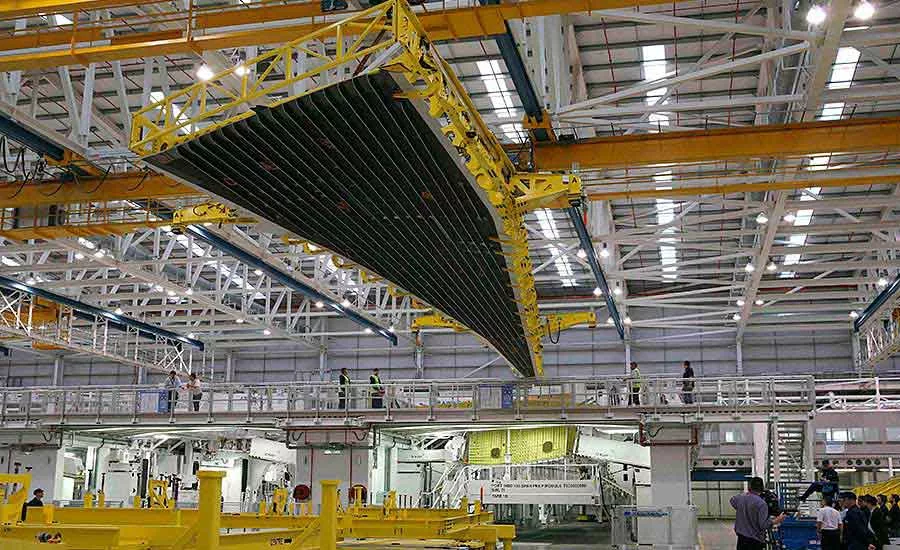
This assembly jig for the A350 XWB wing cover is an example of how aerospace manufacturers assemble compliant structures. Photo courtesy Braunschweig Technical University
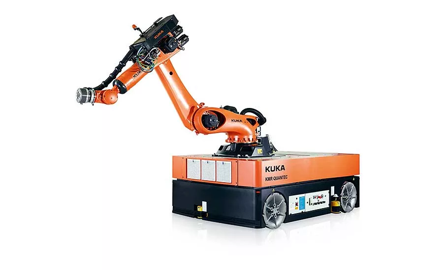
A Kuka KMR Quantec 150 is the base of the AIMM. It consists of a six-axis robot mounted on a mobile platform. As a unit, it can carry a maximum dynamic payload of 150 kilograms. Photo courtesy Kuka
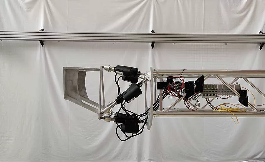
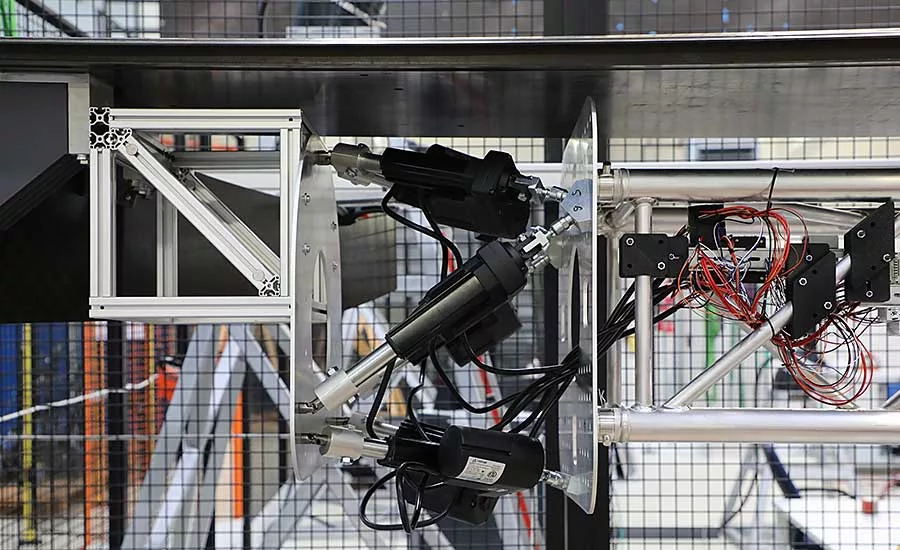
The researchers chose the Stewart parallel kinematic design for its light weight and ability to move with six degrees of freedom. The unit’s electric actuators are controlled by an exernal PLC. Photo courtesy Braunschweig Technical University
This photo shows an early version of the researchers’ end-effector. Subsequent versions were stiffer and stronger. Photo courtesy Braunschweig Technical University
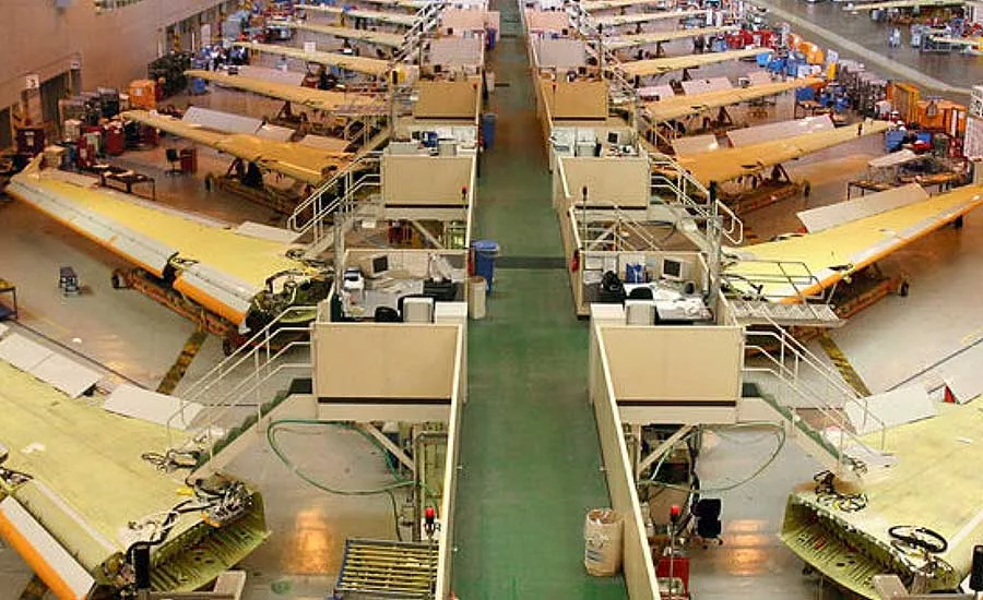
Aircraft assemblers typically use stiff, steel jigs to maintain the geometry of the parts with a high level of precision. Photo courtesy Airbus
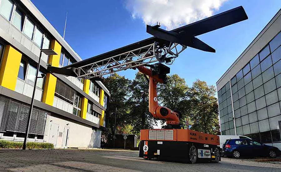
The mobile robot holds the flap in assembly position. Photo courtesy Braunschweig Technical University
Composite structures in airplanes are often thin-walled and lightweight, resulting in significant compliance. This presents a challenge for handling and assembly.
To overcome this challenge, aircraft assemblers typically use stiff, steel jigs to maintain the geometry of the parts with a high level of precision. These jigs have several drawbacks. They take up a lot of space. They are expensive, which limits the possibility of customizing aircraft during production. And, due to their enormous weight, they cannot be moved easily.
An autonomous mobile robot (AMR) could be custom-made to move these jigs. However, it would be expensive, and it would be less flexible than commercial off-the-shelf AMRs. The weight of the jigs must be significantly reduced to enable standard AMRs to move them.
Our research set out to do just that. We developed a unique approach for assembling composite aerostructures using AMRs and lightweight assembly jigs that compensate for deformation. Instead of stiffness, our jig ensures the part’s geometry with active deformation compensation using actuators and sensors in a control loop. Our device—dubbed an autonomous industrial mobile manipulator (AIMM)—is able to assist in all assembly steps of compliant components.
FLAP ASSEMBLY
To test our concept, we put our AIMM to work mounting a flap module to the rear spar of the wing of Airbus’ A320 jetliner. The module consists of the flap body and its supports. Since the flap supports contain the actuators and kinematics needed to move the flap, they account for a significant portion of the module’s weight. To join the module to the aircraft’s wing, studs at the tip of the flap supports must be aligned with, and inserted into, holes in the wing’s rear spar while compensating for deformations in the flap.
An aircraft’s flaps are particularly challenging for assembly. Their slender, tapered design and lightweight construction, along with a mass concentration at the flap supports, tend to create large, weight-induced deformations.
Currently, flaps are mounted in two steps. Assembly starts with the flap supports. They are mounted to the rear spar of the wing and contain all the linkages and actuators. The second step consists of mounting the flap to the flap supports.
Looking for quick answers on assembly and manufacturing topics? Try Ask ASM, our new smart AI search tool. Ask ASM
Flap assembly could be made more efficient by preassembling the flap supports to the flap prior to final assembly. By doing so, cycle time on the final assembly line can be reduced. The preassembled flap system is also called a fully equipped flap. To integrate the fully equipped flap with the airplane’s wing, it must be positioned precisely with the rear spar of the wing. To mount the flap support on the spar, four tapered studs are attached to its tip. These studs must be aligned precisely with bolt holes in the rear spar of the wing. Once aligned, the fully equipped flap is lifted vertically and the tapered studs are slid into the bolt holes. Assembly of the fully equipped flap ends by replacing the tapered studs with proper bolts.
Positioning and joining the studs is challenging due to gravity-induced deformation of the fully equipped flap. The weight of the flap ranges from 300 to 400 kilograms. Due to this deformation, the studs of both supports are not parallel and insertable to the bolt holes simply by positioning the flap with a crane. Force must be applied to the flap to counteract the deformation.
FLAP ASSEMBLY With AIMMs
Our assembly process starts with transporting the fully equipped flap module to the final assembly line with the AIMM. For now, transport is controlled manually. In the future, the AIMM will be able to transport the module to the line autonomously. Automatic assembly starts once the flap is in position.
Traditionally, deformation in the flap would be prevented by supporting it with a stiff, heavy jig. This approach is not feasible with the AIMM. Instead, the AIMM is equipped with a lightweight end-effector that automatically compensates for any deformation.
Several 3D cameras determine the flap’s shape and pose prior to assembly. The cameras can identify the relative positions of the joining features with submillimeter accuracy. Only the joining surfaces of the flap and the wing attachment area need to be aligned. This allows the wing spar to be used as a reference for deformation compensation.
This approach has two main advantages. First of all, only two position sensors are needed. Each sensor measures the relative position of the flap support studs with respect to their corresponding mounting holes within the spar. This allows for a convenient placement of the sensors within the main beam of the end-effector. Secondly, alignment of the studs and the bolt hole pattern will be better.
Wings are compliant and suffer from elastic deformations. Thus, the spar will deform differently depending on the state of assembly and the configuration of the airplane. At first glance, this contradicts usage of the spar as a reference for deformation compensation, since it introduces errors within the shape measurement of the flap. However, this approach will ensure better alignment of the mounting points to each other, since the deformations of the spar are accounted for without additional effort. Therefore, it is efficient only to evaluate the relative positions of the bolt holes and the studs for each side of the flap independently.
The deformation compensation and alignment process consists of two steps. First, the fixed side of the flap is aligned precisely and the movable side is aligned roughly. The first alignment step is achieved by the AIMM’s robot and ends with the studs of the fixed side in a position ready to be inserted into the bolt holes. A precise alignment of both sides with the robot is not possible due to the deformation of the flap. In the second step, the actuators of the end-effector bend the flap so that the studs of the movable side of the end-effector align with the corresponding bolt hole pattern. This bending does not create significant additional assembly stresses, since the flap is mainly bent back to its original shape.
When both sides are aligned, only a movement upwards of the end-effector in the direction of the studs is needed to join the flap component to the airplane.
DEVELOPMENT OF THE END-EFFECTOR
A Kuka KMR Quantec 150 is the base of our AIMM. It consists of a six-axis robot mounted on a mobile platform. As a unit, it can carry a maximum dynamic payload of 150 kilograms.
To design the end-effector, we started with the biggest and potentially heaviest part: the main beam. Aside from weight, the chief design criteria of the beam was stiffness, since the forces applied by the actuators to bend the flap would also act on the beam. We used an aluminum truss for the beam, which has an excellent stiffness-to-weight ratio.
Next, we designed the kinematic for bending the flap. Lateral bending of the flap is most important. However, since the flap and beam are bending in parallel, the kinematic should move on a trajectory, so it bends the flap with minimal internal stresses. The shape and calculation of this trajectory is complex, since the flap is made from non-isotropic carbon-fiber-reinforced plastic. There are several options for bending. The first is to neglect the bending line and bend the flap with a rotational actuation only, which can lead to high internal stresses. The second is to design a mechanism that moves on the trajectory and is driven by one actuator. The third option is to build a kinematic with more than one degree of freedom and generate the trajectory with computer numerical control. We opted for the third option.
Parallel kinematics offer higher stiffness, greater force and lower weight than serial kinematics. Their main drawback is their smaller work envelope. However, since only a few centimeters of bending are needed, a parallel kinematic was the best option for our end-effector. Specifically, we chose the Stewart parallel kinematic design for its light weight and ability to move with six degrees of freedom. The unit’s six electric actuators are controlled by an external PLC.
TESTING ASSEMBLY OF THE FLAP
Our experiments showed that the end-effector can hold the fully equipped flap securely in any position. When the flap is moved by the robot, the end-effector tends to swing significantly. This can be reduced by moving the flap slowly. The motion consists mainly of rotational movement around the robot’s wrist. This can be avoided in the future by using a bigger robot.
Integration of the fully equipped flap starts with alignment of the studs on the fixed side of the end-effector to their corresponding bolt holes using the robot. This alignments was done manually. To insert the studs into the bolt holes with a linear movement, the studs must coincide with their corresponding bolt holes. It is possible to align the studs on the fixed side within a couple of minutes via an iterative approach using the robot’s control panel to move the end-effector and the flap as a whole. Alignment is complete when the tips of the studs are centered within the spar’s bolt holes and the surfaces containing the studs and bolt holes are parallel. Within this alignment step, the movable side was also roughly aligned.
After alignment of the fixed side, the next step is to compensate for the bending of the flap using the Stewart platform. Based on feedback from position sensors, the Stewart platform applies pressure the flap until the studs on the movable side of the flap align with their bolt holes.
With both sides aligned, the integration is completed by the insertion of the studs into the bore holes with a linear motion of the robot. The studs enter the bore holes smoothly and without any jamming. The smooth fit of the studs is assisted by the low stiffness of the AIMM and the flap supports. Only small forces are needed to move the studs horizontally. Stepped bores and tapered bolts also facilitate assembly.
For further research, a thorough investigation of the bending behavior of the whole system is needed. A model to predict the deflection curve of the flap body is needed to account for it when deforming the flap. This model would allow us to lower the internal stresses in the flap and reduce actuation forces. The model needs to describe the bending behavior of both the flap and the end-effector.
In addition, automatic alignment of the flap needs to be tested. Since lowering the stiffness of the robot decreases the need for accuracy in positioning the flap, it seems rational to investigate the use of impedance control for stiffness adjustment.
Looking for a reprint of this article?
From high-res PDFs to custom plaques, order your copy today!


