Ultrasonic Welding of Copper Foils for EV Battery Assembly
Ultrasonic welding is a viable alternative to resistance welding and laser welding for joining copper foils in ev battery cells.
Photo courtesy genkur, iStock / Getty Images Plus
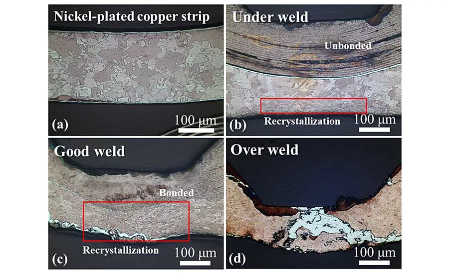
These microscopic images show the differences between good joints, over-welded joints and under-welded joints. Photo courtesy Monisys Co. Ltd.
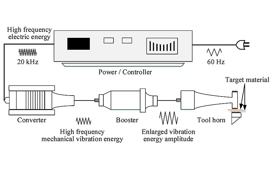
The ultrasonic welder provided a maximum output power of 3 kilowatts and an operating frequency of 20 kilohertz. Illustration courtesy Monisys Co. Ltd.
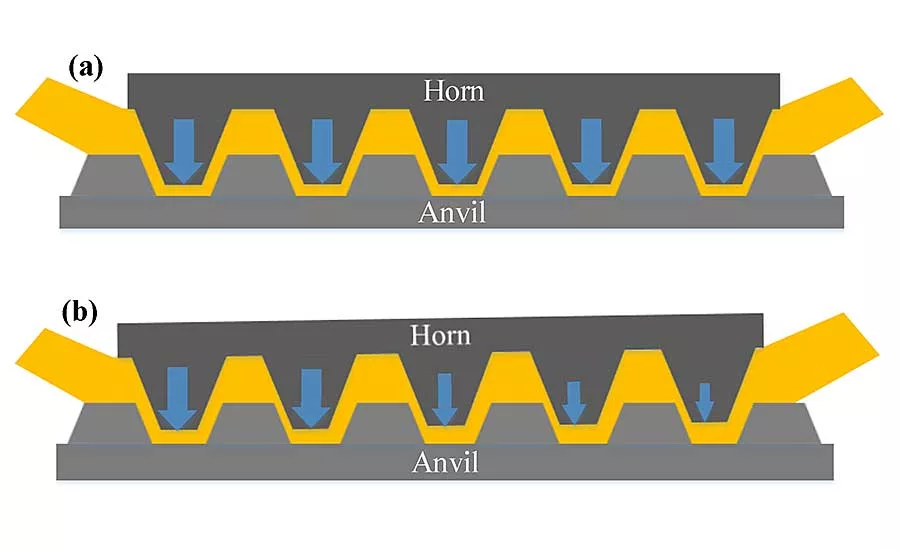
In the case of misalignment (top), less welding energy is generated in the area to be welded. Conversely, if the tooling is aligned (bottom), the welding energy is large since the area that the horn is contacting is relatively larger. Illustration courtesy Monisys Co. Ltd.
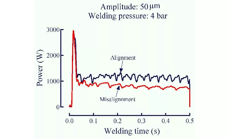
This graph compares the power signals of misalignment and alignment under the same welding conditions. It verifies that when the tooling is properly aligned, the weld energy applied to the joint is higher and therefore the weld will be stronger. Illustration courtesy Monisys Co. Ltd.
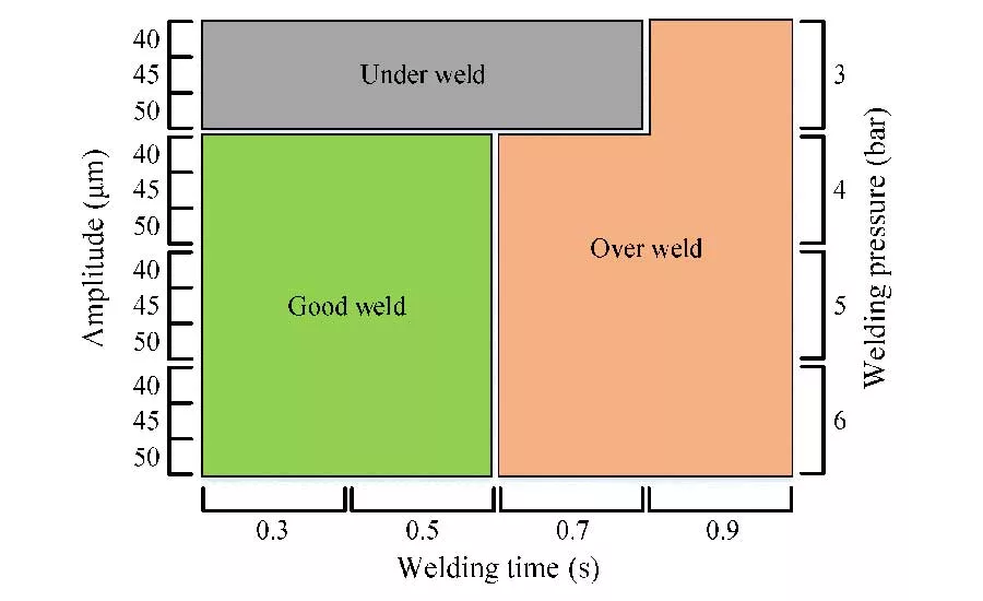
The best welds were produced at a welding force of 3 bar or higher and a welding time of 0.5 second or less. Illustration courtesy Monisys Co. Ltd.
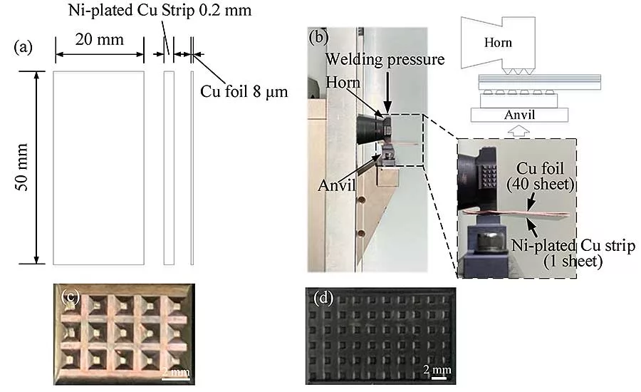
Welding was performed by placing one nickel-plated copper strip on the anvil side and 40 layers of copper foil on the horn side. Illustration courtesy Monisys Co. Ltd.
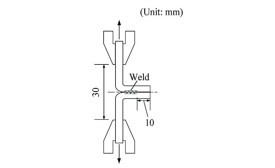
The researchers used the T-peel test to measure the strength of the joints. The welded samples were bent 90 degrees in both directions by separating the tab and the foils to form a T shape. The foils were held by the upper grip and the tab by the lower grip. The test was carried out at room temperature with a crosshead speed of 50 millimeters per minute. Illustration courtesy Monisys Co. Ltd.
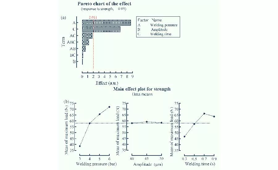
Pareto analysis of the data indicate that welding time and welding force are more important than amplitude for creating a good joint. Illustration courtesy Monisys Co. Ltd.
Batteries for electric vehicles are manufactured by connecting several cells and a bus bar to form a single module. Dozens of modules are then assembled into a battery pack.
Battery cells are connected to multilayered foils and tabs. Materials such as copper and aluminum are used as the main materials.
Resistance spot welding, laser welding and ultrasonic metal welding (UMW) have been used to join foils to tabs. Although resistance welding is advantageous due to its speed and simple automation, it is unsuitable for copper foils, due to their high thermal and electrical conductivity. Laser welding is a high-speed process, but the initial cost of the equipment is high, and it is difficult to ensure quality welds due to copper’s high thermal conductivity, high reflectivity and low absorption rate. Furthermore, a large number of intermetallic compounds are formed during fusion welding, which is difficult to control.
Conversely, the UMW process offers numerous advantages. It’s simple. It can join a wide range of materials. It produces wide welds in a short period of time. And, there is minimal formation of intermetallic compounds and minimal energy loss at the contact part.
Numerous studies have examined the use of ultrasonic energy for metal welding for EV components. Most have focused on single tab-to-tab or tab-to-bus-bar welding. Few have looked at the process of welding multilayered foils to tabs.
Our study examined the use of UMW for joining multiple layers of copper foil to a thin, nickel-plated copper foil strip, a common assembly for high-density lithium-ion batteries. Our study focused on the weldability of the materials; the effect of horn and anvil alignment on production and quality; and the effects of various process parameters, such as force, amplitude and time.
Materials And Methods
The test specimens for our study consisted of a multilayer copper foil (99.99 percent pure copper), 8 microns thick, and a nickel-plated copper strip, 0.2 millimeter thick. Both the foil and the strip were 20 millimeters wide and 50 millimeters long.
Looking for quick answers on assembly and manufacturing topics? Try Ask ASM, our new smart AI search tool. Ask ASM
The ultrasonic welder provided a maximum output power of 3 kilowatts and an operating frequency of 20 kilohertz. Welding was performed by placing one nickel-plated copper strip on the anvil side and 40 layers of copper foil on the horn side.
The UMW process variables included time, amplitude and force. Time was set at 0.3, 0.5, 0.7 or 0.9 second. Peak-to-peak amplitude was 40, 45 or 50 microns. Force was set at 3, 4, 5 or 6 bar.
There is no international standard for evaluating multilayered joints produced with ultrasonic welding. We used the T-peel test to measure the strength of the joints. The weld strength was determined as the maximum load until failure on the load-displacement curve. The welded samples were bent 90 degrees in both directions by separating the tab and the foils to form a T shape. The foils were held by the upper grip and the tab by the lower grip. The test was carried out at room temperature with a crosshead speed of 50 millimeters per minute.
For cross-section analysis, the center of the horizontal line of the indentation mark produced by the horn was observed using optical microscopy and a field-emission scanning electron microscope.
For the purposes of our study, joints were classified as being under-welded, good or over-welded. An under-welded joint produced a maximum T-peel load of less than 40 newtons and showed interfacial fractures. In the case of good welds and over-welded joints, interfacial fractures were not seen. Both good joints and over-welded joints demonstrated a T-peel load of 40 newtons or more. However, the results for over-welded joints were inconsistent, and the foil color was changed. The latter could be an indication that the foil’s properties, such as electrical conductivity, have been adversely affected.
Alignment Effect
If the horn and anvil were misaligned, wrinkles were observed on the weld surface, and the weld cross-sectional shapes showed left-to-right asymmetry. Few wrinkles were observed if the horn and anvil were aligned, and a left-to-right symmetric weld was formed. The welded area was narrower with misaligned tooling than with aligned tooling.
When the tooling is misaligned, the weld tends to fracture between the nickel-plated copper strip and the copper foil. When the tooling is aligned, the fracture is observed only in the copper foil and not in the weld. Therefore, we infer that the fracture is in the copper foil and not the weld, because the strength of the weld is greater than that of the copper foil.
In the case of misalignment, since the horn is asymmetrically set up, less welding energy is generated in the area to be welded. Conversely, when the tooling is aligned, the welding energy is large since the area that the horn is contacting is relatively larger.
Weldability Evaluation
Weldability evaluation was performed without misalignment of the horn and anvil. The experimental conditions were repeated twice with a full factorial design with welding force at four levels, amplitude at three levels, and welding time at four levels.
Our results indicated that average weld strength increases with the increase in welding force, but weld strength is not significantly affected by the amplitude. Additionally, the highest average weld strength was obtained at a welding time of 0.7 second.
Under-welded joints were mostly observed at a welding force of 3 bar. High-strength welds were obtained at a welding time of 0.9 second, but were classified as over-welded joints because of the discoloration of the foils due to the high welding energy. Good welds were produced at welding forces of 4 to 6 bar, and at welding times of 0.3 and 0.5 second. Additionally, the over-welded joints were observed at all welding force levels and at welding times of 0.7 and 0.9 second. Therefore, we concluded that weldability can be ensured at a welding force of 3 bar or more and a welding time of 0.5 second or less.
Cross-Section Analysis
Cross-section analysis verified our determinations of under-welded, over-welded and good joints.
With under-welded joints, cross-sections show an unbonded region in the weld where the horn knurl is engaged with the anvil. This is observed at low welding forces and short welding times.
With over-welded joints, thinning is observed in the weld where the horn knurl is engaged with the anvil, and cracks exist on the slope of the outer sheets. These two phenomena reduce weld strength. Additionally, we infer that the thinning and cracking are caused by the excessive energy applied to the joint. These defects are not observed in good welds.
FE-SEM analysis revealed that the nickel-coating on the strip has a distinctly continuous interface in under-welded joints, which indicates that there is no metallurgical bond between the foil layers and the strip. In the nickel layer, the coating is observed all the way to the top of the weld in over-welded joints, which is considered as a driving force for the occurrence of thinning due to excessive plastic deformation. The nickel layer exists discontinuously by pushing and moving down to the lower part of the weld in a good weld, indicating that there is a metallurgical bond between the foil and the strip.
The main purpose of nickel plating is to prevent corrosion and enhance the weldability of highly conductive materials. This is because nickel has a higher thermal and electrical resistance than copper. For battery applications, the joints require high conductivity. Therefore, when the nickel layer is discontinuous at the interface, the electrical energy loss in the joint could be reduced.
Conclusions
Based on our experiments, we draw the following conclusions:
- Alignment of the horn and anvil are important for weldability.
- Amplitude was almost unrelated to joint strength, but welding force and welding time correspond with weld strength.
- The best welds were produced at a welding force of 3 bar or higher and a welding time of 0.5 second or less.
Editor’s note:
This article is a summary of a research paper co-authored by Sangwoo Nam, Jiyoung Yu, and Dongcheol Kim of the Korea Institute of Industrial Technology in Incheon, South Korea; and Jiyong Park of the University of Science and Technology in Daejeon, South Korea.
ASSEMBLY ONLINE
For more information on ultrasonic welding, visit www.assemblymag.com to read these articles:
Ultrasonic Welding Provides Integrity to Wire Harnesses
Looking for a reprint of this article?
From high-res PDFs to custom plaques, order your copy today!


