Plastics Assembly: Design for X
These tips will help engineers design plastic parts for optimal performance whether they’re welded, bonded or fastened.

One of the great benefits of making parts out of plastic is that they can be assembled in many different ways. Plastics can be joined by ultrasonic welding, vibration welding, spin welding, hot-plate welding, laser welding, induction bonding, staking, snap fits, press fits, adhesives, solvents and threaded fasteners.
No matter how the parts will be assembled, engineers are well-advised to consider the joining method as they are designing the parts. Often, a small change-widening a hole, thickening a wall or adding a gusset-can mean the difference between a smooth assembly operation and one hamstrung by constant process faults. Whether the assembly will be welded, bonded or fastened, technology suppliers can provide invaluable guidance on part design.
“The fastener is usually the last thing engineers think of when designing an assembly,” bemoans Larry Pickett, marketing director at fastener supplier Acument Global Technologies Inc. (Troy, MI). “Sometimes, we can live with that if the parts are metal, but with plastic, we need to be involved as close to the drafting board as we can get.”
“The earlier we are involved in the process, the better,” adds Brian Gourley, manager of the technical services group and Sonics & Materials Inc. (Newtown, CT). “We’ve been joining plastics for years, so we can troubleshoot a process in advance.”
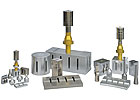
When designing parts for ultrasonic welding, engineers should provide enough room for the tooling to contact the parts. The horn needs adequate surface area to transfer energy to the parts, and the fixture must be able to locate the parts underneath the horn and support the area to be welded. Photo courtesy Sonics & Materials Inc.
Ultrasonic Welding
When designing plastic parts for ultrasonic welding, engineers have several options for joint configurations.A butt joint with an energy director is the most common design and the easiest to mold. An energy director is a small triangular-shaped ridge molded into one of the mating surfaces. The energy director limits initial contact to a very small area and focuses the ultrasonic energy at the apex of the triangle. The concentrated energy melts the ridge and plastic flows throughout the joint area, bonding the parts together.
For a stronger bond and a more aesthetic appearance, engineers can use a step joint with an energy director or a tongue-and-groove joint with an energy director.
Joints with energy directors are not recommended for welding crystalline materials when high strength or hermetic seals are required. Instead, a shear joint should be used. With a shear joint, initial contact is limited to a small area, usually a recess or step in one of the parts. The contacting surfaces melt first. As the parts telescope together, they continue to melt along the vertical walls. For best results, the top part should be as shallow as possible, the outer wall should be well-supported by the fixture, and one part should have a chamfer to help the assembly slide together.
Regardless of joint design, engineers should provide enough room for the tooling to contact the parts. “The horn needs adequate surface area to transfer energy to the parts without leaving any marks behind. I like to see an area at least 0.125 inch wide for the horn to contact,” says Gourley. “The fixture needs to locate the parts underneath the horn and support the area you’re trying to weld.”
The parts should be thick enough to withstand both the pressing force and the vibrational energy. “I like to see a minimum of 0.08 to 0.1 inch,” says Gourley. “If it’s less than that, the part will not be stable enough to melt. It will actually move with the horn or experience sympathetic motion.”
If engineers can’t make the part thicker, a reinforcing feature, such as a gusset, might stabilize the part enough to weld. Parts as thin as 0.0312 inch have been welded successfully.
Tolerances are critical. “If the molder can maintain a tolerance of ±0.005 inch, that will satisfy 95 percent of ultrasonic welding applications,” says Gourley. “If the parts are out of tolerance, ultrasonic welding will not make them better.”
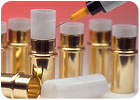
When designing plastic parts for adhesive bonding, engineers should maximize the surface area to which the adhesive can bond. Photo courtesy Dymax Corp.
Adhesive Bonding
For adhesive bonding, the parts should be designed so that the joint is only subjected to tensile or sheer stresses. Exposure to cleavage and peel stresses should be minimized, and the entire bonded area should share the load equally.“When designing plastic parts for adhesive bonding, the goal is to maximize the surface area for the adhesive to bond to,” says Dave Christiansen, technical services specialist at Ellsworth Adhesive Systems (Germantown, WI). “You want the substrate to fail before the adhesive.”
A simple lap joint is the most common configuration for adhesive bonding. However, thin parts could be vulnerable to peel and cleavage stress, warns Christiansen. A tapered lap joint is more efficient; the tapered edge allows bending of the joint edge under stress. A joggle lap joint, a double-butt lap joint or double-scarf lap joint provide even more stiffness and distribute stress more uniformly than either simple or tapered lap joints.
An angle joint-bonding one part perpendicular to another part-is susceptible to both peel and cleavage stress. To reduce those stresses, engineers can design pins or tabs into the edge of the part to be bonded. The part would then fit into a groove and matching holes in the base part. Alternatively, engineers should provide a wide flange on the base of the bonded part.
“When there’s little surface area to bond, and there’s a high load on the joint, it’s a good idea to include some kind of mechanical brace in the design,” says Kyle Rhodes, market segment manager for medical devices and plastic bonding at Dymax Corp. (Torrington, CT).
A straight butt joint has poor resistance to cleavage. A recessed butt joint, such as a tongue-and-groove design, is stronger and helps align the parts.
“With a tongue-and-groove design, you want a low-viscosity adhesive-1,000 to 2,000 centipoise or less,” adds Rhodes. “A low-viscosity material will pool along the bottom and fill the groove.”
Depending on the adhesive, engineers should shoot for a bond-line thickness of 4 to 6 mils. In fact, says Rhodes, engineers can save money on molding costs by taking advantage of the gap-filling ability of the adhesive. Because the parts can have a looser fit, they can be molded at looser tolerances and thus are less expensive to produce.
The choice of material is usually dictated by the application requirements. However, if engineers have some latitude in choosing the materials, they should avoid plastics with low surface energy, such as polyethylene, polypropylene and polyolefin. “Acrylics and polycarbonates are easy to bond,” says Christiansen.
The choice of adhesive can also influence the joint design. For example, if light-curing adhesives are used, engineers should ensure that energy can reach the entire joint. “You want to avoid shadowed areas,” says Rhodes.
If shadowed areas are unavoidable, suppliers can provide adhesives with more than one curing mechanism, such as formulations that cure when exposed to light and heat, light and moisture, or light and a catalyst.
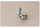
The threads of the Delta PT thread-forming screw for plastic have a 30-degree flank angle. This improves material flow during installation, providing better clamp load and increased joint strength. Photo courtesy Acument Global Technologies Inc.
Threaded Fasteners
When designing plastic parts for assembly with threaded fasteners, engineers should focus on several key dimensions, says David C. Goss, principle engineer at Acument. Depending on the fastener and the flexural modulus of the material, the outside diameter of the boss should be 1.8 to 2.5 times the diameter of the screw. The diameter of the hole should be 0.8 times the diameter of the screw, and the depth of the hole should be at least twice the diameter of the screw.The right fastener is also critical. Engineers should choose a fastener designed specifically for plastics. Compared with the threads of standard screws, the threads on screws for plastics are more widely spaced and have a narrower flank angle. As a result, the threads exert less radial stress on the boss, which prevents cracking, and they capture more material, which increases pull-out strength.
Engineers also need to choose between thread-forming and thread-cutting screws. Thread-forming screws are less expensive than thread-cutting screws and offer the most resistance to backing out. However, thread-forming screws should not be used in plastics with a flexural modulus over 200,000 psi. These materials are too stiff to take the radial stress of forming threads. If a thread-cutting screw is necessary, engineers should provide room between the end of the fastener and the bottom of the hole to collect the plastic chips shaved from the boss.
Fillers and other additives can affect how screws behave in the plastic. For example, fillers added to increase impact resistance often make a plastic more ductile than its flexural modulus would otherwise indicate. A lubricant added to facilitate molding can reduce driving torque and negatively affect clamp load.
Because every plastic behaves differently, it’s a good idea to test several screws in the application. To obtain statistically significant results, engineers should test at least 30 sample assemblies with each screw, and the fastening tool used in the test should run at the same speed as the tool on the assembly line. For optimal fastening, driver speed should be kept under 600 rpm.
When evaluating screws, engineers should compare strip-to-drive ratios. This is the ratio between the torque at which the screw will strip its threads and the torque necessary to drive it. Ideally, this ratio should be at least 4-to-1.
Looking for a reprint of this article?
From high-res PDFs to custom plaques, order your copy today!


