Wire Processing: CAD Keeps Pace With Complexity

Rapid growth in vehicle electronics and embedded software is putting huge demands on engineers who design automotive electrical systems. Compounding the problem, the number of vehicle configurations is growing. Yet somehow, vehicle makers must reduce costs and improve reliability.
Fortunately, the electrical system design process is evolving. A broad selection of software tools, known as electrical computer-aided design (ECAD) applications, offers aid and comfort to beleaguered automotive designers.
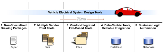
Five generations of tools have brought us to the data-driven automation construct that is emerging today. These generations overlap; there is no clean dividing line from one to the next.
The first generation of software, introduced in the mid-1970s, embodied the earliest nonspecialized design tools. These applied the power of desktop computers to improve design productivity, allowing engineers to render their designs neatly and make changes easily. But, this software added no design intelligence and produced no design data. Basic electrical calculations-even using Ohm’s law to determine a wire’s cross section-had to be accomplished offline.
Later, the first specialized ECAD applications emerged. These second-generation tools added graphical schematic authoring, and linked schematic representations to engineering data via explicit electrical object models. A line on a drawing represented a true electrical connection between pins on components. Connections could be associated with attributes, such as length and cross section. Component and symbol libraries ensured consistency and reduced errors.
But, most second-generation tools covered a small portion of the overall electrical design process and therefore were considered “point tools.” A fully integrated system might require multiple tools sourced from different (often competing) vendors and employing dissimilar data structures. While more efficient than earlier tools, the second generation had high IT maintenance costs and tended to perpetuate historical-sometimes obsolete-design processes.
The third generation resolved many of these challenges by addressing more of the design process. A single design environment might support electrical design, simulation, harness engineering and assembly, including production of form boards. Third-generation tools employ file-based design data storage mechanisms, and can be cost-effective when the electrical design task is moderately complex.
With the fourth generation of tools, the concept of data-centricity arrived. All relevant data-from user privileges, to device connectivity, to component relationships-was lodged within a relational database rather than in flat files. This form of data storage is key to solving some of the problems of modern electrical design complexity, particularly in configuration complexity and design change management. For example, relational database storage inherently supports “where used?” queries, conditional replacement (“replace this component if that is true”), and design version comparison. Fourth generation software also brings in Web-based integration and computing platform independence, substantially reducing IT costs.
That brings us to the present day and the fifth generation of ECAD tools, which deliver truly advanced design automation, complete with process-spanning business logic automation. This new generation takes direct aim at today’s complexity issues by deploying powerful features, such as generative design, failure analysis and data management.
Generative Design
Generative design is fast becoming the cornerstone of electrical system design in vehicles. What’s different about the generative approach? Wiring designs are automatically generated from higher level inputs, rather than interactively constructed by an engineer working with a lesser tool.
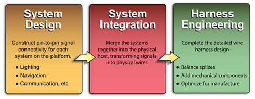
The typical electrical design process consists of three steps: system design, system integration and harness engineering.
System integration is a difficult and error-prone task, especially with rising signal count and configuration complexity. Imagine a semi tractor. These trucks are available with a huge variety of options and many mechanical configurations, such as different wheelbases. Complicated configuration logic applies: It’s impossible to have both right- and left-hand drive simultaneously, but it is possible to have left-hand drive, a long wheelbase and a satellite theft-tracking system simultaneously. Millions of individual electrical configurations are possible. Engineers must keep track of all possible configurations, while ensuring that in-line connectors mate correctly and pass signals from one harness to another.
In the generative design process, system integration and development of wiring proceed automatically, based on simplified input expressions. The “ingredients” include:
* System pin-to-pin signal connectivity. Each signal is tagged with an expression defining the options it supports. This is a comparatively straightforward design task.
* Mechanical constraints, such as routing channels, bundle lengths and in-line connector locations. These are typically developed within 3D mechanical CAD systems. Mechanical constraints may also reflect configuration variables, such as alternative wheelbases.
* Configuration logic, which expresses the relationships between the configuration variables. These consider such things as the impossibility of building a vehicle with both right- and left-hand drive.
* Design rules, which enforce the design methodology of the engineer and the enterprise as a whole.
These four independent inputs are all that is required to calculate automatically the wiring for the entire vehicle for the superset that includes every configuration the logic allows. This calculation accomplishes system integration entirely within the ECAD tool.
The design rules are the key to the generative process. They capture the designer’s skills, and more broadly the intellectual property of the designing organization. The rules instruct the ECAD tool’s algorithms how to proceed. The sum of all the rules is a substantial body of required and forbidden states that must be adhered to. Rule sets may be hierarchical and dynamic. They may even act on data retrieved from outside the CAD data environment.
Rule sets are normally company- or project-specific. Examples include:
* “Never permit more than six wires in any splice”
* “Never permit wires of the same color to occupy adjacent connector cavities.”
The generative approach creates designs that are correct by construction. If the four “simple” input expressions are written correctly, the software will automatically generate accurate wiring designs for all allowable configurations.
There is much more to generative design than just rule checking, though the rule sets do robustly implement best practices, allowing organizations to capture and develop their competitive intellectual property. System integration is rapid, accomplishing in a few hours a task that would otherwise take weeks. This not only reduces electrical design times and costs, but also allows the evaluation of alternative designs, sometimes by applying different rule sets.
Design change management is greatly simplified, too. Because the four inputs are independent, a design change affecting just one of the inputs (for example, a change of configuration logic) can be propagated through the process easily.
Find Failures Before They Occur
The latest ECAD software can perform failure effects analysis. The knowledge gained from these analyses can be used to fine-tune a design so failures become less likely, and the effects of failure less serious.While failure mode effects analysis (FMEA) is widely recognized as a key contributor to product safety and reliability, rigorous electrical FMEA is difficult, especially as design complexity expands.
FMEA operating within ECAD applications builds on electrical simulation capabilities to probe possible failure events. To accomplish this, models are built within the software to define the state of each device in response to all possible electrical inputs. Designers catalogue failure modes, assign probabilities and then build scenarios describing the effects of error states, which may range from an incorrect dashboard indication to a dangerous brake system flaw. Severity ratings are assigned to each effect, and detectability metrics assigned to each failure.
With these inputs and explicit knowledge of the electrical design, the FMEA software can cycle through every possible failure mode, and combinations of modes, to generate specific risk measures.
The FMEA exercise can be scoped to various levels: to an individual system, a group of systems, or even to every configuration of the entire vehicle. The software ranks the risk measures and describes them in natural language, allowing engineers to take corrective action.
In addition to generating FMEA reports, the most advanced ECAD software can dynamically identify erroneous connectivity, such as sneak circuits, and even recommend certain design improvements.
Design Data Management
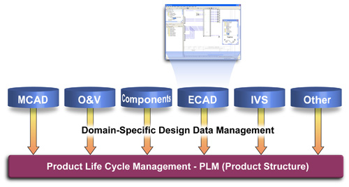
At the highest levels of ECAD performance, design data management is central to the tools’ value-creating functionality. The ability to manage and interrogate design data flexibly is the core enabling technology.It’s important to recognize the difference between ECAD design data management and large-scale corporate product lifecycle management (PLM) systems. ECAD tools provide automation in the electrical design domain. The data model and associated functionality are specialized for this task. Other design domains, such as mechanical CAD, are served by equally specialized tools.
In effect, the design tools are subordinated to the PLM system. Specialized design tools receive data, such as component library data from the product data management (PDM) environment residing at the platform level, and then release completed designs back to the PDM for storage and communication. But, the design task that occurs between these events is best accomplished using domain-specific tools. These may communicate directly with one another or via the PLM system.
Looking for quick answers on assembly and manufacturing topics? Try Ask ASM, our new smart AI search tool. Ask ASM
Looking for a reprint of this article?
From high-res PDFs to custom plaques, order your copy today!


