Choose the Best Parts for Your Wire Harness
Each component of a wire harness can affect the performance of the finished product
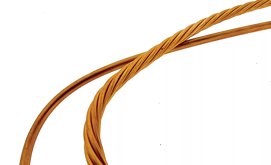
Stranded conductors (right) are more flexible than solid conductors (left). Both are bare, unplated copper. Photo courtesy Epec Engineered Technologies
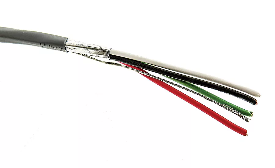
This cable consists of individual insulated conductors wrapped with a foil shield and enclosed by a polymer sheath. Photo courtesy Epec Engineered Technologies
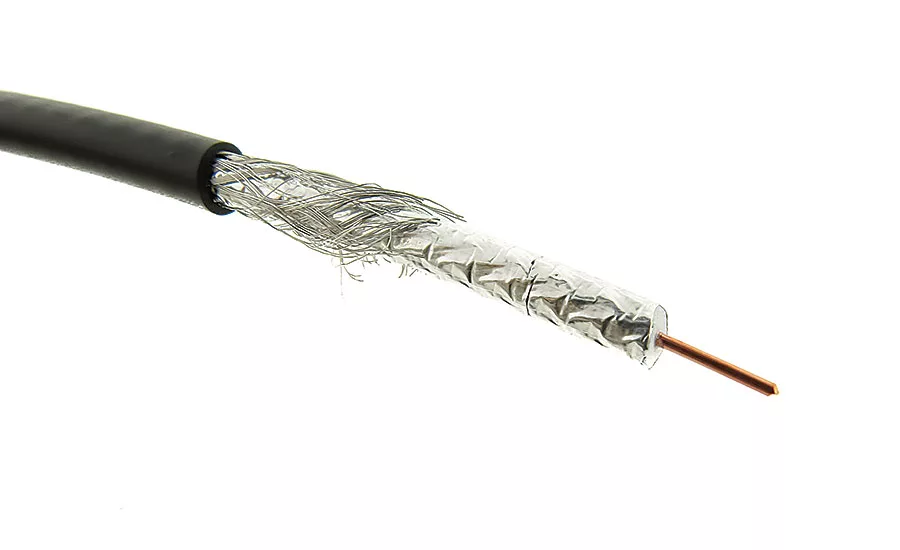
This cable has both foil and braided shields to control electromagnetic and radio frequency interference. Photo courtesy Epec Engineered Technologies
A key component of any electronic or electrical system is the cable assembly or wire harness—and yet it is typically one of the last components to be addressed.
When designing a system, the wiring should be addressed as early in the design stage as possible. A wiring harness has many components—including connectors, wraps, clips, seals, and, of course, the wires themselves—and each can affect the performance of the finished product. An overdesigned or underdesigned wire harness could ultimately have a negative impact on the performance of the finished product.
When designing a wire harness, engineers have many questions to answer up front. Some of the biggest involve the environment in which the harness will be used. Will it be exposed to flexing? Will it be in a clean room? Will be exposed to sunlight or moisture? Will it be exposed to chemicals or temperature extremes?
Conductor or Circuits
The number and type of circuits or conductors that are included in an assembly will be determined by the application. Many options are available for the type of conductive material, the stranding of the conductors, and the plating applied to the materials.
The most versatile and widely used conductor material is copper. Copper is compatible with numerous coatings to retard corrosion and to aid in the termination process. If more breaking strength in the conductors is needed, options such as copper-clad steel and copper alloys are available. These materials still employ copper, but add either steel or alloys, such as cadmium, chromium and zirconium, to increase both flex life and breaking strength. In some limited applications, stainless steel can be used as a conductor, though stainless steel by itself is a poor conductive material compared with copper and may have to be plated to improve its conductivity.
Bare copper is prone to corrosion when exposed to the atmosphere, so most conductors are plated with various coatings to both retard corrosion and to allow copper to be used in more rigorous installations. One of the most popular and least expensive coatings is tin. It retards corrosion and aids in the termination process. If the cable assembly will be exposed to higher temperatures, coatings such as silver or nickel can be applied. These coatings enable conductors to be used reliably at temperatures of 200 C and 260 C respectively.
The conductors can consist of a single solid strand of conductive material, or they can be constructed of many thin strands. Stranded conductors were developed as a means of overcoming the rigidity of solid wires and come in many variations. For any given size conductor, the higher the number and the smaller the diameter of the strands, the more flexible the conductor.
Looking for quick answers on assembly and manufacturing topics? Try Ask ASM, our new smart AI search tool. Ask ASM
Each conductor of the cable assembly should be designed for its specific use. For instance, if a conductor will provide power, the amount of current it will carry must be considered before determining the size of the conductor to use. If a conductor will transmit a signal, then signal speed and the length of the assembly must be considered to determine the optimal construction of the conductor.
Insulation and Sheathing
Insulators are available in either thermoset or thermoplastic compositions, and as with conductor construction, the material, thickness and type of insulation of the primary conductors will be determined by the application. Materials are available to meet a broad range of applications and environments. Some of the critical areas to address are the operating temperature; the type and level of voltage that the assembly will carry; the harshness of the operating environment, and the types of chemicals and fluids the assembly will be exposed to.
Materials are available to handle temperatures from -65 C to 200 C or higher. A factor that needs to be addressed when thinking about temperatures is whether the assembly will be in a dynamic or a static state. In other words, will the assembly be subject to movement? And if so, at what temperature? An assembly that will be in a dynamic state at extreme temperatures will need more rugged insulation to enable it to function properly.
The amount of current or voltage carried by the cable assembly will also determine the type of insulation to be used. Some insulation materials are not able to handle high currents for extended periods of time.
If higher speed signals are to the transmitted, some insulation materials will be “foamed” using either a chemical process or a gas-injection process. This process creates air bubbles in the insulation, allowing the passage of the high-speed signal without being impeded.
The primary insulation can be colored and marked for identification purposes. Coloring is completed by using a colorant that is mixed with the compound during the primary extrusion stage. An additional method of identification is by either printing a number on the insulation or by applying a stripe, which can be longitudinal, spiral or bands.
Twisting Conductors
Invented by Alexander Graham Bell in 1881, the twisting of wires is done to cancel out electromagnetic interference from external sources. The most common noise problem is with cables used for telecommunications applications, where pairs in the same cable are next to each other for long distances. Because of the proximity, one pair can induce crosstalk onto an adjacent pair and this noise is additive along the length of the cable. Twisting the pairs of a cable counters this effect, because the pairs are only near each other on the half twist. If an assembly will be used for communications or a data signal transmission, twisted pairs should be considered to eliminate any risk of noise or EMI.
The conductors or twisted pairs can also be cabled together. Cabling is a manufacturing operation where the conductors or pairs are helically wrapped, or “cabled,” together. The cabling serves several purposes. It provides for a more flexible assembly, and it produces a round configuration that will allow for an aesthetically pleasing assembly.
Shielding
To further control both electromagnetic and radio frequency interference, shields can be applied once the conductors are cabled together. There are several options for shields. Each has its advantages and disadvantages. One of the most popular shields is a metalized foil adhered to a polyester backing, known as a foil shield. The foil shield is the least expensive. It has fairly good flexibility, but not good flex life. It is good at higher frequencies, but it’s less effective at low frequencies.
Another option for a shield would be a braided shield. This type of shield is composed of many small-diameter wires that are braided onto the cable core using specialized equipment known as braiders. This type of shield is more expensive than a foil shield, but is more difficult to terminate. It offers better shielding at lower frequencies and provides for better flex life.
A different type of shield is a spiral shield, in which small diameter wires are wrapped around the cable core. This type of shield provides excellent flexibility with long flex life, but is poor at protecting at high frequencies and is difficult to terminate.
The best protection against interference comes from a combination of foil and braid shields. This combination provides excellent protection at all frequencies and is easy to terminate. However, it’s usually the most expensive option.
Outer Sheath
When the cable core is finished, an outer sheath or jacket is applied. This jacket is a protective covering and is called upon to be flame retardant to meet UL and CSA requirements. The outer jacket must also be physically tough to protect the cable from harsh environments, flexible to allow movement of the assembly during installation and operation, chemically resistant, and semi-conductive in some applications.
The jacket can be made from many materials, depending on the end-use environment. PVC is the most widely used and cost-effective compound. Other materials include urethane-based products for severe-service applications; elastomer-based products; fluorocarbons for fire resistance and physical toughness; alloy-based materials; and non-halogen materials, which produce low smoke, low toxicity and low acid when exposed to fire.
Connectors and Strain Reliefs
Many options are available for connectors. The type and speed of the signal being transmitted will drive the connector choice. For instance, if power is to be sent through the assembly, a crimp-type connector could be chosen. If a high-speed signal is to be transmitted, a soldered or welded connection will be used. The options for a connector could be limited based on the assembly in which the harness will be installed. If the final assembly is already equipped with a certain type of connector, terminal choices will be limited.
Strain relief also needs to be addressed. The strain relief provides a transition point from the cable to the termination area and prevents a load applied to the cable from being transferred to the terminations, causing termination failure. Options for strain relief include a solid or segmented design. The segmented design provides the greatest amount of bend relief, but is more difficult to keep clean if used in sterile environments.
Safety Certification
One of the major concerns when designing a cable assembly or wire harness is location—that is, the region of the world where the assembly will ultimately be used, that region’s safety certifications, and the environmental standards that need to be met.
Many countries have their own regulatory and safety standard agencies that enforce the examination and testing of electrical devices. For instance, in North America, UL and CSA are the regulatory and safety standard agencies that set the guidelines for electrical devices.
Beyond North America, most countries will have their own safety agencies. Most countries use IEC (International Electrotechnical Commission), CEE (International Commission for Rules for the Approval of Electrical Equipment), or CENELEC (European Committee for Electrical Standardization) as the basis for their guidelines.
There are also environmental standards that limit or restrict the use of hazardous substances in products. WEE, REACH and RoHS directives are three such standards that limit the use of hazardous substances. The WEEE Directive governs the disposal and recycling of electronic and electrical products when products are at the end of their usable life.
In addition to safety and environmental standards, assemblies may also need to meet industry standards based on specific performance criteria. Depending on the application, the cable assembly may need to meet criteria such as HDMI, SFP+, QSFP, TIA/EIA 568-C.2, or the assembly may need to be verified by an independent testing service such as ETL.
In the end, every specification of the design must be addressed up front before manufacturing can begin. Disregarding these important factors could hurt the performance of the final product and could also affect the price of the product. If you are designing a product that requires a cable assembly, it is always a best practice to bring up all the application details with your harness manufacturer to help determine the best cable assembly to suit your needs.
Looking for a reprint of this article?
From high-res PDFs to custom plaques, order your copy today!


