The Impact of the LV 214-4 Standard
A new standard developed by German automotive OEMs provides insight into crimp force monitoring.
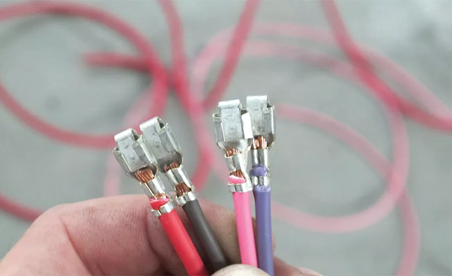
Developed by German carmakers, the new LV 214-4 standard outlines the requirements for terminals for automotive wiring. Photo courtesy American Autowire Inc.
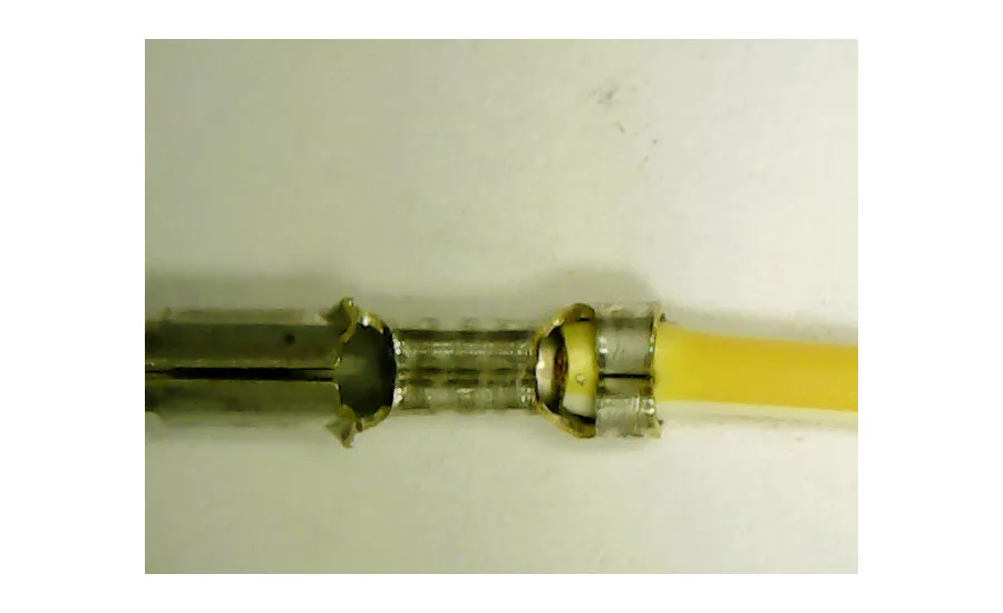
A. LV 214-4 defines what an empty crimp is. In a good crimp, the conductor crimp is filled with all wire strands, while the insulation crimp contains all the undamaged insulation material (photos B and D). Crimp parameters are at the nominal values as specified by the manufacturer. An empty crimp has a full insulation crimp, but the conductor crimp is empty (photos A and C). Photos courtesy Schleuniger Inc.

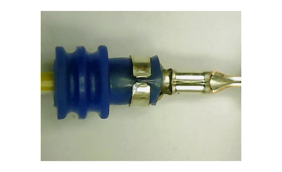
B. LV 214-4 defines what an empty crimp is. In a good crimp, the conductor crimp is filled with all wire strands, while the insulation crimp contains all the undamaged insulation material (photos B and D). Crimp parameters are at the nominal values as specified by the manufacturer. An empty crimp has a full insulation crimp, but the conductor crimp is empty (photos A and C). Photos courtesy Schleuniger Inc.
C. LV 214-4 defines what an empty crimp is. In a good crimp, the conductor crimp is filled with all wire strands, while the insulation crimp contains all the undamaged insulation material (photos B and D). Crimp parameters are at the nominal values as specified by the manufacturer. An empty crimp has a full insulation crimp, but the conductor crimp is empty (photos A and C). Photos courtesy Schleuniger Inc.
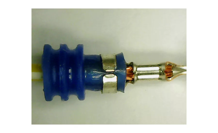
D. LV 214-4 defines what an empty crimp is. In a good crimp, the conductor crimp is filled with all wire strands, while the insulation crimp contains all the undamaged insulation material (photos B and D). Crimp parameters are at the nominal values as specified by the manufacturer. An empty crimp has a full insulation crimp, but the conductor crimp is empty (photos A and C). Photos courtesy Schleuniger Inc.
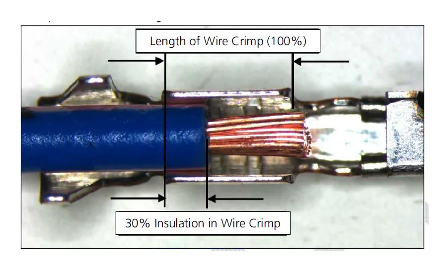
Under the LV 214-4 standard, a crimp force monitor must be able to detect an assembly with 30 percent insulation inside the crimp. Photo courtesy Schleuniger Inc.
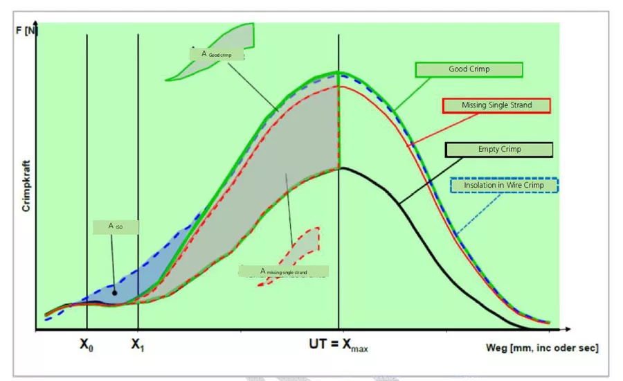
For many years, crimp force monitors have analyzed the total area under the crimp curve. However, the new LV 214-4 standard defines four area segments: one for good crimps and one for each error mode (empty crimp, missing strands and insulation-in-the-crimp). Illustration courtesy Schleuniger Inc.
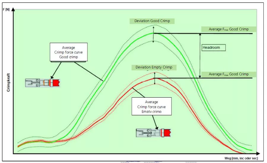
Headroom is the difference between the peak forces of the average good crimp and empty crimp curves, also expressed as a percentage. Illustration courtesy Schleuniger Inc.
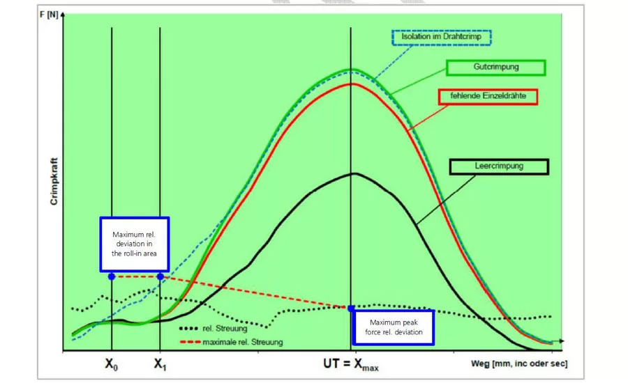
The LV 214-4 standard provides a formula to determine specific locations for X0 and X1. X0 is generally where the good crimp and the insulation-in-the-crimp curves begin to diverge. X1 is generally where the good crimp and empty crimp curves begin to diverge. Illustration courtesy Schleuniger Inc.
It goes without saying that every manufacturer wants to ensure they are assembling a quality product. Standards and specifications from various organizations provide a guideline from which manufacturers can measure different aspects of quality, while also providing the customer with the reassurance that they are purchasing a trustworthy, long-lasting product.
Within the wire processing industry, there are many standards that manufacturers may choose or be required to adhere to. These standards and specifications are constantly evolving and increasing in detail, especially as monitoring technology improves.
One of the newest wire processing standards is LV 214-4, an automotive standard developed by German car manufacturers Audi, BMW, Daimler, Porsche and Volkswagen. The standard outlines terminal requirements specifically for the automotive industry. The standard addresses the ability of terminals to be effectively evaluated by crimp force monitors. To be used in an automotive wire harness, a terminal must exhibit certain crimp force characteristics so that typical crimp force monitors can effectively detect critical error modes.
Though it is currently in draft form and many points are still largely theoretical, the standard has been in progress for many years.
Concepts: Old and New
The standard focuses on relative deviation of force curves and headroom, both common concepts with regard to crimp force monitoring. Relative deviation is the variation of peak force expressed as a percentage. Headroom is the difference between the peak forces of the average good crimp and empty crimp curves, also expressed as a percentage.
LV 214-4 defines what an empty crimp is, something that is not clear to all. In a good crimp, the conductor crimp is filled with all wire strands, while the insulation crimp contains all the undamaged insulation material. Crimp parameters are at the nominal values as specified by the manufacturer. An empty crimp has a full insulation crimp, but the conductor crimp is empty.
For many years, crimp force monitors have analyzed the total area under the crimp curve. However, LV 214-4 defines four area segments: one for good crimps and one for each error mode (empty crimp, missing strands and insulation-in-the-crimp). The good crimp area is the area between the good crimp curve and the empty crimp curve. Similarly, the missing strand area is the area between the missing strand curve and the empty crimp curve. Alternatively, the area for insulation-in-the-crimp is the area between the insulation-in-the-crimp and the good crimp curves. Differences in each of these areas must be detectable for the corresponding error mode.
Looking for quick answers on assembly and manufacturing topics? Try Ask ASM, our new smart AI search tool. Ask ASM
The LV 214-4 looks closely at the “roll-in” portion of the crimp. The roll-in area is the beginning of a crimp force curve, where the terminal wings begin to roll in and close around the wire. Most monitors ignore this portion because forces are usually inconsistent, and this part of the crimp process is not very important. However, LV 214-4 analyzes relative deviation and defines the positions X0 and X1.
X0 is generally where the good crimp and the insulation-in-the-crimp curves begin to diverge. X1 is generally where the good crimp and empty crimp curves begin to diverge. The LV 214-4 standard provides a formula to determine specific locations for X0 and X1.
At this time, however, no crimp force monitor analyzes the area under the crimp curve as described in the LV 214-4 standard. Similarly, the force curve data in the roll-in area is typically ignored during monitoring with filters. Therefore, the different area regions, X0 and X1 are theoretical and will only be considered during initial validation of the terminal.
Today’s crimp force monitors detect area differences as a result of crimp defects, but analysis does not go to this detail. However, the LV 214-4 standard is not a specification for crimp monitors; it is a specification on terminal characteristics. Regardless of how the area results are calculated, the LV 214-4 standard mandates that, when crimped, a terminal must exhibit significant differences in these areas so that a crimp force monitor can accurately detect all scenarios. If not, it will not be approved for use in an automotive harness. Furthermore, typical crimp monitors are used on the production floor. Therefore, if the terminal is already on the production floor, it has already been approved, so this level of detail in the analysis is not required.
Feasibility Study
The feasibility study is the testing methodology for terminals as defined under LV 214-4. It is to verify that defect modes can be detected for a terminal-and-wire combination. The output identifies the separation between good crimps and defective crimps. Tests must be performed using the smallest wire allowed for that terminal. For example, if the terminal is rated for 18 to 22 AWG wire, 22 AWG wire should be used for testing. Although the procedure is written for initial validation of terminals, this process can be used on the production floor to determine the feasibility of any application.
After the application is set up, crimp parameters have been verified, and the teach crimps are completed, 300 good crimps and five empty crimps are processed. The relative deviation of the good crimp peak forces is calculated. The LV 214-4 standard specifies a maximum relative deviation of 1 percent. If the relative deviation is greater than 1 percent, the terminal fails for this criterion and the testing stops. If the relative deviation is less than 1 percent, the terminal passes and the test continues.
The next step is to test crimps with strands missing. The LV states that 9 percent missing strands must be detectable. Examples are given for calculating the 9 percent and rounding up for various wire sizes. For example, in a seven-strand wire, 9 percent missing strands equals 0.63 (7 x 0.09). Rounding up, that means a crimp force monitor must be able to detect one missing strand from the crimped connection. For a 32-strand wire, a crimp force monitor must be able to detect three missing strands (32 x 0.09 = 2.88).
Ten crimp samples are processed with the required number of missing strands and all must be detected as defects. If all the defective crimps are detected as defects, the terminal fails and the test stops. If all 10 are detected as defects, the test proceeds.
The next step is to detect insulation in the crimp. Like with missing strand detection, 10 wires must be processed with insulation in the crimp area and all must be detected as defects. LV 214-4 mandates 30 percent insulation inside the crimp for these tests and provides a clear method of measurement. If all are not detected as defects, the terminal fails and the test stops. If all are detected successfully, the test continues.
At this point, the operator considers the headroom. LV 214-4 states that headroom should be greater than 35 percent. Headroom can actually be determined much earlier on in the feasibility test. However, it is best left for last. If the terminal fails any test up until this point, the terminal does not meet the criteria of the specification and thus cannot be used in an automotive wire harness. However, if all defects are successfully detected, but the headroom value is less than 35 percent, then perhaps special parameters are required.
Documentation
The final area discussed in LV 214-4 is documentation. To meet LV 214-4 criteria, proper documentation must be kept of all assembly data, machine data and the results of all testing. This includes terminal ID, crimp data, wire cross section, wire type, machine, applicator and crimp force monitor used, relative deviations, headroom, and feasibility study results. This data is used not only for internal purposes, but can also be shared with customers or manufacturers to help them understand why a specific terminal is or is not appropriate for their application.
It is important to remember that LV 214-4 is intended for terminal validation in automotive harnesses. This means that when an OEM receives a terminal that has been approved for automotive manufacturing, all of this testing has already been completed. However, the LV 214-4 is a culmination of knowledge from top automotive manufacturers and provides consistency among expectations and processes in terminal requirements for automotive use. Thus, it is important for OEMs to have at least a basic knowledge of what the LV 214-4 standard is and how it may affect their manufacturing.
Looking for a reprint of this article?
From high-res PDFs to custom plaques, order your copy today!


