Ingress Leak Testing
Engineers have a couple of options for determining if fluids can penetrate an assembly.
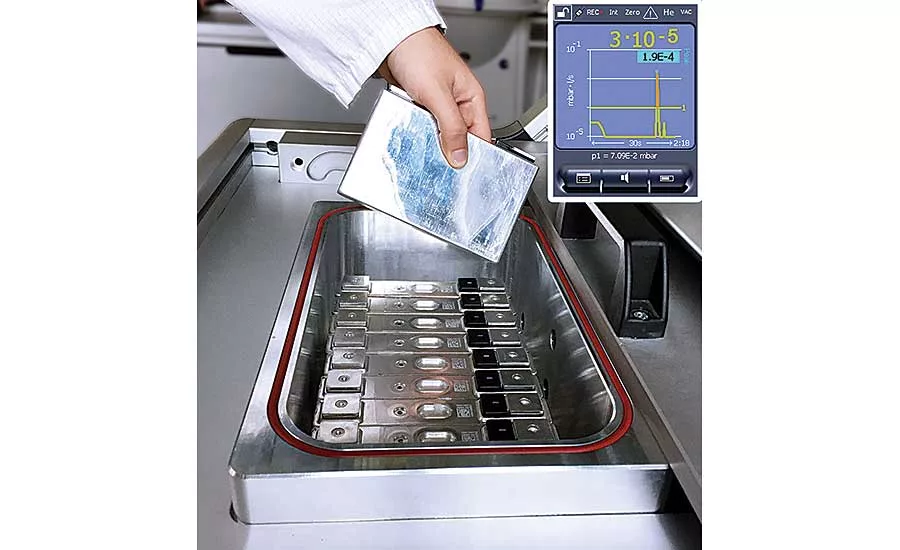
Battery cells for electric vehicles are leaktested at an Inficon facility in Cologne, Germany. Testing of individual battery cells after production and again prior to assembly into battery packs is critical to ensuring battery pack longevity. Photo courtesy Inficon
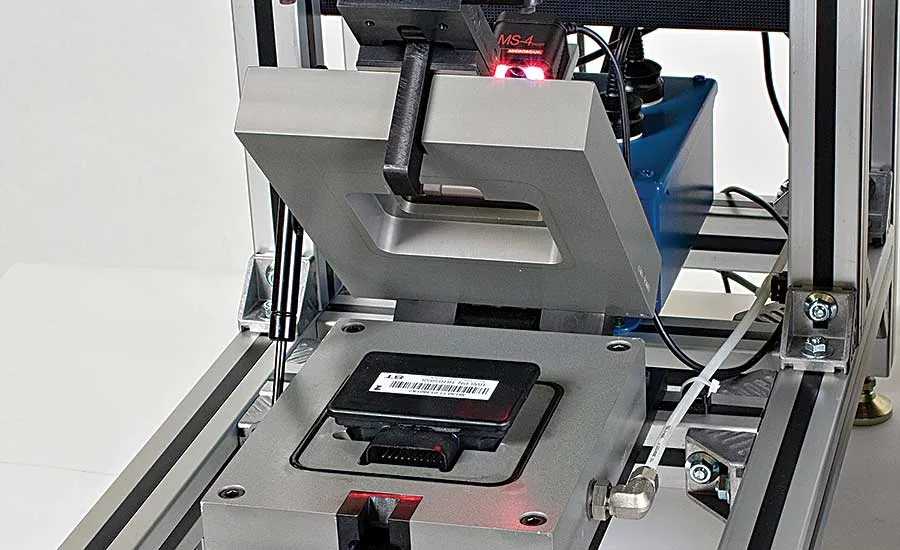
two-step test cycle checks this electronic control module for gross leakage and then fine leakage to a limit of 0.6 standard cubic centimeters per minute and 10 percent gauge R&R. Photo courtesy InterTech Development Co.
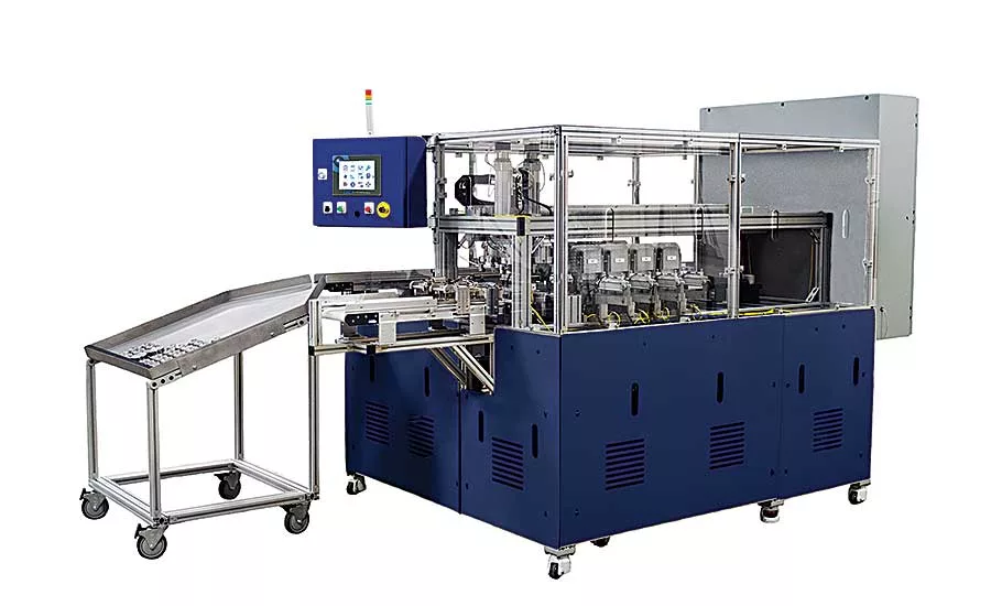
This automated test system uses helium to check air bag inflators for leaks. Photo courtesy Laco Technologies Inc.
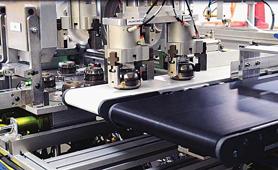
Leak rate specifications for ingress testing are typically stricter than for outflow tests, particularly for assemblies like these air bag inflators. Photo courtesy Laco Technologies Inc.
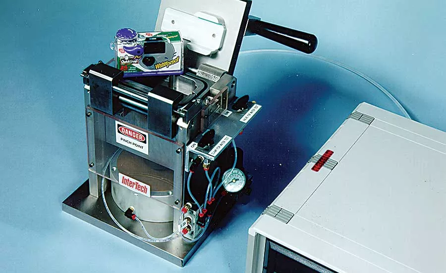
This system was designed to test a waterproof camera to a limit of 0.5 standard cubic centimeters per minute at a rate of 180 parts per hour. Photo courtesy InterTech Development Co.
Since 2008, 28 million cars have been recalled in the United States because they contained air bags that could explode and hurl shrapnel into drivers during even minor fender benders. Ten deaths and more than 100 injuries have been linked to the faulty air bags.
Ultimately, the problem was traced to the solid propellant, ammonium nitrate, used to inflate the air bag. When the propellant was installed in the inflator, it was typically in the shape of a wafer or bat wing. However, it changed shape when exposed to humidity over time. When the air bag was triggered, the change in the propellant’s shape led to an unexpected increase in pressure that detonated the inflator instead of filling the air bag. The force of the explosion would hurl pieces of the inflator into the cabin like shrapnel, injuring those in the vehicle.
Investigators concluded that the inflator’s design was not sufficient to protect it from heat and humidity. Today, every air bag inflator is rigorously tested to determine if water, humidity or other fluid can penetrate the assembly.
Ingress Leak Testing
Most leak testing applications are aimed at determining whether a liquid or gas could escape from an assembly. Less common—and more difficult—are leak tests to determine if liquids, gases or dust can penetrate into an assembly.
Also known as inflow leak testing or enclosure integrity testing, ingress leak testing is performed on many types of auto parts besides air bag inflators. These include headlights, engine control units, rearview cameras, tire pressure sensors and batteries for electric vehicles. Medical device manufacturers do ingress tests on implantable devices, such as pacemakers, and wearable devices, such as heart monitors and insulin pumps. Avionics and military electronics, such as ring laser gyroscopes, undergo ingress testing, as do smartphones, underwater cameras, wristwatches and other consumer products.
Ingress leak testing is not the same as outflow leak testing. For starters, determining a leak rate specification can be problematic.
“With outflow testing, you often have a product that is pressurized with gas—a refrigeration component, for example—and you don’t want to lose more than, say, 0.1 ounce of refrigerant per year. From there, you can run calculations and correlate the results to a leak rate using helium as a tracer gas,” explains Paul Chamberlain, president of Laco Technologies Inc.
Looking for quick answers on assembly and manufacturing topics? Try Ask ASM, our new smart AI search tool. Ask ASM
“With inflow testing, it can be more challenging to determine a leak-rate reject limit,” he continues. “The first step is to make sure we understand the operating conditions of the product. Will it be submerged? Implanted in a person? Exposed to weather? Will it see different altitudes? What is the internal pressure? Typically, if you’re worried about ingression, the product is probably at atmospheric pressure. What conditions might drive a contaminant into the product?”
Determining an inflow leak rate specification is rarely straightforward. Empirical studies may be necessary to determine what an ideal leak rate might be for a given product. At Laco Technologies, for example, applications engineers will sometimes subject assemblies with known leaks to various environmental conditions just so they can learn how and why contaminants could get inside.
The nature of ingress leak testing makes coming up with a leak rate specification difficult, says Guy Dewailly, president of ATEQ Corp. “It’s difficult, because the leak rate will change with time on a sealed component,” he explains. “There’s a finite amount of space inside the component, so the longer you test it, the less the leak rate will be. Pressure will build up inside the part.
“It’s not like testing for leaks to the outside, where there’s a direct correlation between a drop in pressure and a leak to the outside.”
Thomas Parker, automotive leak testing sales manager at Inficon, says leak rate specifications for ingress testing are typically stricter than for outflow tests. “Implantable medical devices…are tested at 10-9 millibar-liter per second. That’s a very low, hard-to-get-to leak rate,” he says. “For air bag inflators, the leak rate might be 10-6 or 10-7 millibar-liter per second, depending on whether it’s a solid pyrotechnic material or a stored gas model.”
Ingress leak rates are stricter because it’s easier for water vapor to make its way into an assembly than it is for, say, motor oil to leak out of one. “Think of it like an army of ants as opposed to a herd of elephants,” says Parker.
Test Methods
Engineers have a few options for ingress leak testing.
One option is to connect the interior of the assembly to a vacuum source and attempt to pull air or a tracer gas into the product from the outside. However, this method is not the most ideal. That’s because the vacuum can draw the parts of the assembly together, closing off potential leak paths and making the assembly seem more leak-tight than it really is.
The most common method of ingress leak testing is a pressure decay test. The assembly is placed in a chamber, which is then pressurized with air. At a predetermined pressure, the chamber is cut off from the pressure source. If there’s a leak, air will flow into the assembly, causing the pressure inside the chamber to drop. The leak rate can then be calculated based on the change in pressure over a certain period of time.
A variation on the pressure decay method is the mass-flow method. The test part is placed in a chamber. The chamber and a reservoir are pressurized to test pressure, then isolated from the pressurizing source. If the test part leaks, the pressure inside the chamber will force air into the part. Since the reservoir remains at test pressure, air will flow from the reservoir into the chamber to maintain equilibrium. A mass-flow transducer, located between the reservoir and the test chamber, measures that air flow, providing a direct assessment of how badly the assembly is leaking.
“The advantage of positive pressure over vacuum is that it will be more searching,” says Jacques Hoffman, president of InterTech Development Co. “It simulates actual operation, whereas when you pull a vacuum, you might be closing up leaks.”
With either the pressure decay or the mass-flow method, it’s important that the test instrument check for gross leaks prior to looking for fine leaks, says Dewailly. An assembly with a gross leak is essentially open to the atmosphere. Thus, the air pressure inside the assembly will instantly be identical to the air pressure in the chamber. In other words, there will be no pressure loss inside the chamber, and an assembly with a gross leak will appear to be good.
Gross leak detection is accomplished by controlling the volume of air used to charge the chamber and monitoring the final pressure. Failure to achieve test pressure in a specific time indicates a gross leak.
“When you put a known volume of air inside the test chamber, you would expect pressure to reach, say, 2 psi, if the component is good,” explains Dewailly. “But if the component is wide open, the chamber will only reach 1.5 psi.”
For pressure decay testing to work, the assembly must have enough internal volume that the test instrument can detect a gross leak. In addition, the amount of “dead volume”—the volume between the interior of the chamber and the exterior of the part—is a major factor in the cycle time of the test. The larger the dead volume, the longer the cycle time.
That’s why test chambers are typically custom-made for each assembly. It’s also a good idea to keep the test instrument close to the test area, to minimize the amount of air in hoses.
Although the size of the test assembly isn’t that important for pressure-decay testing, the materials do matter. The pressure decay method cannot be used to test flexible components. “We can’t test, say, a balloon,” says Dewailly. “If you pressurize the outside of a balloon, it would just collapse in on itself. The pressure will build up instantaneously and equate between the inside and outside.”
This Method is the Bomb
Another option for ingress leak testing is a technique known as “helium bombing.”
In helium bombing, a batch of assemblies is placed in a chamber and exposed to helium at a set pressure for a set length of time. If an assembly has a leak, helium will gradually seep into it. Next, the assemblies are removed from the helium chamber and placed, one at a time, in a second chamber and a vacuum is drawn. A mass spectrometer then looks for helium leaking from the assembly.
This is how air bag igniters are tested. For example, InterTech recently designed a helium bombing system that automatically tests small air bag igniters to a leak rate specification of 10-6 standard cubic centimeters per second at a rate of 1,800 parts per hour. The igniters were approximately the size of a medication capsule.
That latter aspect is important, since the bombing technique works best with smaller assemblies. “Helium bombing is only suitable for small devices, because they have a small internal volume,” says Chamberlain. “It’s not practical to pressurize parts with large internal volumes. The cycle times become unreasonable.”
“Bigger parts have more surface area, which can retain ambient humidity and helium. That can slow down cycle time,” adds Parker. “When testing larger parts, companies will often have more than one test unit to meet throughput.”
Handling time is also important with the helium bombing method. “You have to get the part from the bombing chamber into the testing chamber rather quickly, because helium could leak from the product on its own [without the aid of vacuum]. You can’t wait days to test those [bombed] parts,” advises Parker. “Parts can be in that chamber for hours. Some companies have recipes calling for four to eight hours in the helium chamber.”
As an alternative to the bombing technique, some air bag manufacturers seal small amounts of helium into inflators during assembly. Depending on the manufacturer, this helium may have a functional role in the air bag, or it may simply be added to facilitate subsequent leak testing.
Either way, the inflator is placed in a sealed chamber and a vacuum is drawn. As with the bombing technique, a spectrometer detects helium leaking from the assembly.
“The challenge with that method is that you’re measuring helium leaking out from the part when you’re actually concerned about gas leaking into the part,” says Chamberlain. “It’s not the ideal test, but it’s adequate. We would prefer to test the part…under the same conditions that it will see in use.”
Looking for a reprint of this article?
From high-res PDFs to custom plaques, order your copy today!


