How to Determine a Torque Specification
The best fastening technology is only as good as the specifications they’re designed to maintain.
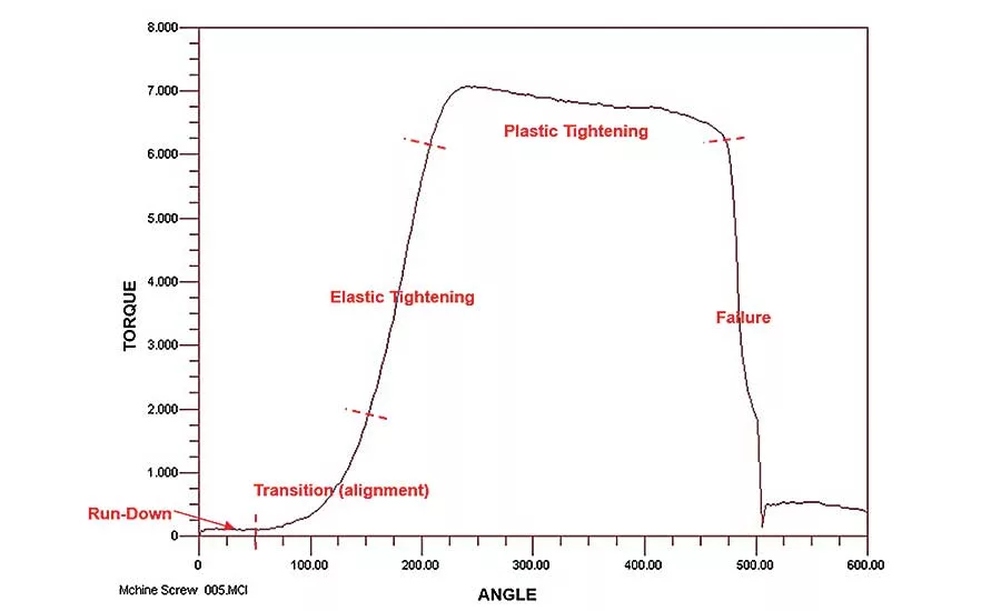
Plotting a torque-angle curve for a series of run-downs can help engineers set a torque specification for an application. Illustration courtesy Peak Innovations Engineering
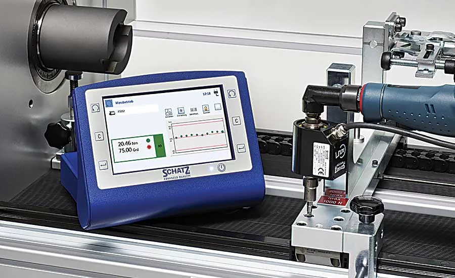
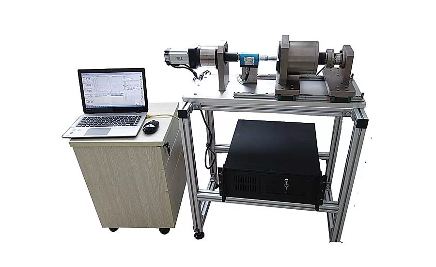
Test equipment like the SCHATZ-INSPECTpro enables engineers to determine specifications for torque and angle. Photo courtesy Kistler Instrument Corp.
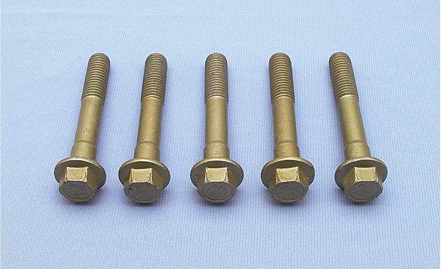
Because they affect friction, platings, coatings and lubricants have a significant influence on the torque specification. Photo courtesy NOF Metal Coatings North America Inc.
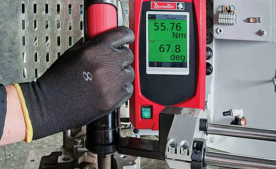
Regardless of test method, tests should be run using actual production parts. Photo courtesy Desoutter Industrial Tools
The UNIVER TOK-3001 torsion testing machine is used to verify the suitability of high-strength bolt, nut and washer assemblies for a particular application. Photo courtesy Univer Technologies Group
A slew of technology is available to ensure threaded fasteners are installed in the correct sequence and at the correct torque and angle.
For example, Ingersoll Rand’s QE Series of DC electric tools and IC Series of controllers measure torque with an accuracy of ±0.2 percent and angle to ±1 degree. Measurement resolution is ±0.025 percent of full-scale torque. Engineers can implement numerous tightening strategies, including torque control; torque control with angle monitoring; torque control with yield override; angle control; angle control with torque monitoring; angle control with yield override; yield control; prevailing torque; and drag torque. The tools come in pistol-grip, inline and angle-head versions, and the series covers a torque range of 0.3 to 400 newton-meters.
Of course, even the most accurate tools are only as good as the specifications they’re designed to maintain. A whole lot of engineering work must be done before a socket ever hits a bolt head. Engineers must determine the type and number of fasteners needed to secure the joint. They need to consider platings, coatings, lubricants and thread-lockers. They need to think about how the fastener will be installed. Is it enough to tighten the fastener to a specific torque? Or will both torque and angle need to be controlled? Once all that’s decided, engineers must establish specifications for torque, angle and fastening sequence.
“There are a lot of variables associated with tightening threaded fasteners, [and the torque specification] is not an absolute. It’s a guide, actually,” says Guy T. Avellon, president of GT Technical Consultants Ltd., a consulting firm that provides training and analysis of bolted joint design. “You throw in lubrication, different coatings, tolerances, and a host of other things. There’s even a difference between tightening the nut and tightening the bolt head.”
Regardless of the product, everything starts with calculating how much clamping force is needed for the assembly to operate correctly and safely. This is determined by the loads and conditions to which the joint will be exposed, plus a safety factor.
Engineers must choose a fastener or fasteners that can successfully transmit that clamping force between the parts and bear the stress of it. But all fasteners have limits to how much stress they can take. This is a function of the fastener material and its geometry, including its cross-sectional area and the area of the threads. That limit cannot be exceeded.
The goal is to tighten the fasteners enough to achieve the specified clamping force, but not so much that the fastener can’t bear the stress. How much torque that requires depends on the geometry of the bolt and whether the threads are lubricated. (Lubricated threads require less torque to get to the same clamping force, because there is less friction to overcome during the tightening.)
Looking for quick answers on assembly and manufacturing topics? Try Ask ASM, our new smart AI search tool. Ask ASM
Calculating Torque
There are two ways to come up with a torque specification: “The right way and the wrong way,” quips David Archer, principal engineer at Peak Innovations Engineering, a consulting firm specializing in bolted joint design and analysis.
The wrong way, asserts Archer, is to pick a number off a standard engineering table or to rely solely on the classic equation, T = KDP, in which T is the target tightening torque; K is the coefficient of friction, or nut factor; D is the nominal diameter of the bolt; and P is the desired tensile load on the bolt.
“K is your friction variable,” explains Avellon. “It’s a constant, but it’s a constant variable, because K is related to finishes like a black oxide or zinc plating. Are you using moly lube or copper anti-seizing lubricant? Even threadlockers can act as a lubricant initially.”
The most commonly used K factors arc 0.2 for plain finished bolts, 0.22 for zinc-plated bolts, and 0.1 for waxed or highly lubricated bolts. For a more accurate estimate of the nut factor, engineers can set up a standard fastening test to solve the equation for K.
“The equation is fairly accurate, but every application should be evaluated on its own to determine the optimum torque value,” advises Avellon.
“The equation is fairly accurate, but every application should be evaluated on its own to determine the optimum torque value.”
– Guy T. Avellon
The best way to develop a torque specification is through testing, argues Archer. The reason to do testing is that friction, run-down speed, part tolerances and other variables can significantly influence the relationship between torque and clamp load.
Two types of tests can be run to determine a torque specification: measuring torque and angle to failure and measuring torque and angle to a specific tension. “Torque-angle to failure is simpler. You need less complex equipment…but it’s probably not as accurate,” says Archer. “Torque-angle to tension is more accurate, but it requires some means of measuring either bolt tension or clamp load.”
In either case, the goal is to find a torque value that applies the most clamp load on the joint without the risk of tightening the fastener past its yield point or, worse, its breaking point.
Regardless of test method, tests should be run using actual production parts. “Don’t use prototypes, because they tend to made with different processes, materials and finishes,” advises Archer. “And, you should never reuse the bolts, because the whole point of testing is to understand the frictional characteristics of the assembly. If you reuse a bolt, you will get different characteristics each time.”
The number of run-downs needed to determine a torque specification varies. “For practical reasons, that number is influenced by the value of the parts, because at least some of the parts are going to be destroyed in the process of testing,” says Archer. “A common average is a dozen run-downs. A typical range would be six to 24 run-downs.”
In a torque-angle to failure test, engineers perform several run-downs, plotting torque vs. angle of rotation, and tightening the fastener until it fails. The goal is to find the yield point of the fastener.
Every fastener has a certain amount of elasticity as it is stretched. If the load is removed and the fastener is still within its elastic range, the fastener will return to its original shape. However, if the fastener is tightened past its yield point—past the elastic range and into the plastic range—it will no longer return to its original shape if the load is removed. The fastener is permanently elongated. Tightening the fastener past this point will, ultimately, cause it to break.
The installation torque specification would then be some percentage—perhaps 75 to 85 percent—of the average torque value when the fastener reached its yield point, plus or minus two or three standard deviations, Archer explains. Alternatively, the installation torque could be set at a smaller percentage—say, 60 percent—of the average torque value when the fastener failed.
Measuring torque and angle to a tension requires a load cell, a strain-gauge bolt, or an ultrasonic sensor. “The benefit of the ultrasonic method is that there’s no functional change to the joint. You’re not modifying the bolt or adding an extra part to the joint, so there’s no risk that the measurement method altered the test results,” says Archer.
An ultrasonic sensor measures bolt tension in real time. By establishing a fixed acoustic path between the sensor and the fastener, there is no measurement variation due to coupling between the sensor and bolt. Ultrasonic technology also allows long-term monitoring of joint tension to asses stability in use or after dynamic testing.
The torque-angle to tension test is performed in the same way as the torque-angle to failure test. Sample joints are tightened to the yield or failure point of the fastener. In this case, however, engineers are looking for torque that produces a specific clamp load.
From Spec to Strategy
Once an installation torque has been set, engineers must then decide how to implement that specification on the assembly line. Should the tool shut off at a specific torque or a specific angle?
“It’s more common to shut off at a torque,” admits Archer. “It’s simpler and you don’t need an encoder.
“Since you’re not measuring actual clamp load during production…you have to pick a torque value that will get you that clamp load most reliably,” adds Archer. “If the high end of your torque specification is 80 percent of the yield value…the low end should be based on the capability of the fastening tool.”
Angle-controlled tightening is more accurate. “The whole point of doing torque vs. tension testing…is because the relationship between torque and clamp load is so affected by variations in friction,” says Archer. “When you’re tightening to a specific angle of rotation, friction is not a part of that. You are elongating the bolt by some fixed amount. There’s a much more direct correlation between rotation and stretch of the bolt.
“By the way, bolt elongation is not simply a matter of calculating the pitch of the fastener vs. the angle of rotation, because there will be some compression of the joint members as well as elongation of the bolt.”
To implement angle-controlled tightening, engineers will need fastening tools that can measure angle accurately. “It’s not enough to say, ‘That looks like a half turn.’ With joints that are very stiff, a 10-degree error can mean a big difference in results,” Archer warns. “You want a tool with a built-in encoder that can measure angle with an accuracy of 0.25 to 1 degree.”
Looking for a reprint of this article?
From high-res PDFs to custom plaques, order your copy today!


