Defining Fastener Head Strength
Recent fastener failures during tensile testing have highlighted the need for a better understanding of the dynamics of the head-to-shank juncture

High-strength threaded fasteners are critical components in the assembly of virtually every form of transportation and industrial machinery. Industry-accepted standards for the measurement and performance of these critical parts have existed for decades, but recent failures of threaded fasteners in service and qualification testing are bringing new focus to the critical area between the head and shank of the fastener. This juncture has been highly analyzed in large-diameter (0.5 inch or more), high-strength, externally wrenched bolts (hex head, 12 point, etc.) used in automotive and aerospace applications, but less attention has been paid to the many bolts and screws below this threshold.
Recent qualification failures of M5 diameter fasteners made to a European standard have brought new focus on this issue. The aerospace industry has always been concerned with the weight of the airframe structure, and the thin materials used in airframe construction necessitate the use of 100-degree countersunk flush-head fasteners. These thin-profile heads—as well as other low-profile designs intended to reduce weight in aerospace, automotive and industrial applications—present unique challenges for the design of an effective torque transfer mechanism (internal or external) while still assuring head-to-shank integrity.
Fastener standards development organizations and fastener engineers focus their attention on developing part standards that provide attributes (length, diameter, head diameter, head height, etc.) that can easily and accurately be measured to confirm conformance to form and fit requirements. Unfortunately, it is difficult to accurately measure the critical stress area between the top of the shank of the fastener and the bottom of the internal recess or lightening hole in an externally wrenched head without destroying the fastener to perform the measurement.
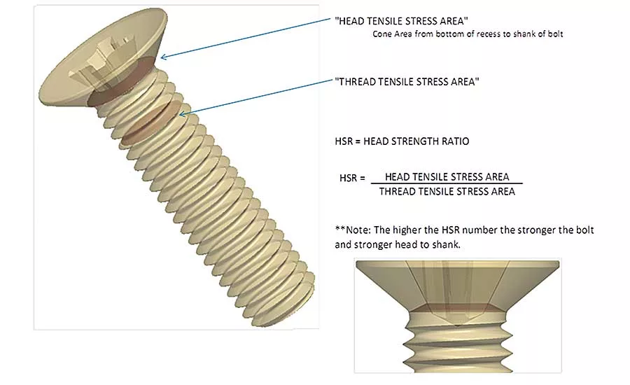
A consensus must be reached on how to calculate the head strength ratio (HSR) to achieve the minimum acceptable tensile strength for the head-to-shank juncture and what method and measureable data should be used in the calculation.
The Problem
During recent reviews of qualification test data for aerospace screws (100-degree countersunk head, six-lobe recess, threaded to head, titanium alloy TI-P64001, anodized, coated with molybdenum disulfide, and classified to 900 megapascals at ambient temperature to 350 C), it was found that a batch of M5 diameter parts failed to meet the required tensile test limits with lower than required failure levels in the head-to-shank juncture. Through investigation, it was found that the parts had previously been qualified by analogy to a standard for a different aerospace screw: pan head, six-lobe recess, coarse-tolerance normal shank, medium-length thread, titanium alloy, anodized, coated with molybdenum disulfide, and classified to 1,100 megapascals at ambient temperature to 350 C.
In short, the presumed analogous standard was for a different head style, a different shank configuration, and a higher material strength. Additionally, because of the different head style and shank configuration, the pan head part has a much different head-to-shank juncture geometry than the fastener with the 100-degree countersunk head that is threaded to the head. Given the differences between these designs and materials, what method or data should be used to qualify similar or dissimilar parts by analogy or to evaluate the potential tensile strength of a given head-to-shank geometry?
A poorly designed head and recess configuration can result in fasteners that fail to meet tensile strength requirements with higher than expected failure levels at the head-to-shank juncture.
Looking for quick answers on assembly and manufacturing topics? Try Ask ASM, our new smart AI search tool. Ask ASM
Defining the Variables
The variables in the head-to-shank juncture of a fastener that influence tensile strength can be limited to the effective geometry of the interface, while the tensile strength of the threaded portion of the fastener can be based on the effective tensile stress area of the thread itself. We must define the diameter to be used to calculate the effective tensile stress area of the portion of the fastener as it transitions from a threaded area to an unthreaded area. That “effective diameter” is different for a given thread geometry (10-32UNJF, for example) when it transitions to an unthreaded shank than when it transitions from a fully threaded part to the underside of the fastener head.
In a bolt, the thread transitions to a full body diameter (0.19 inch for our 10-32 UNJF example). The result is that the weakest tensile stress area occurs at the thread pitch diameter one or two threads below the thread-to-full body transition. The thread pitch diameter is often equivalent to the blank diameter (the diameter of the unthreaded fastener before the thread profile is rolled onto the base material).
In the case of a fastener that is threaded to the head, the minimum tensile stress area often occurs in the area between the last full thread and the bottom of the head or the thread-to-head transition zone. Here, the effective tensile stress diameter may be the same as the thread pitch diameter (a minimum of 0.1658 inch for our 10-32UNJF example), or it may be slightly smaller if this area is fillet-rolled to relieve stress built up during the manufacturing process.
This is significant, because the difference in the effective tensile stress area in the head-to-shank transition will be different for a full-body bolt than for a threaded-to-the-head screw. The stress cone—or the effective cross-sectional area between the shank-to-head transition and the bottom to the internal recess—is calculated using either the larger diameter of the bolt transition or the smaller diameter of the fully threaded transition.
The calculation of the HSR then becomes a comparison of the effective tensile areas to the full-shank diameter for a bolt or the thread pitch area for a fully threaded screw. Ideally, the HSR will always be 1 or greater, so that a tensile failure of the fastener will always be at or above the minimum tensile strength of the thread pitch diameter. This assures that there is enough strength in the head-to-shank juncture to avoid popping the head off the fastener and failing the joint.
Figure 1 shows the tensile stress areas in the thread profile (shaded areas) and in the head-to-shank juncture area for a fully threaded fastener. Note in the head cross section that the stress area goes from the under-head diameter, which is approximately the thread pitch diameter, to the nearest point of the bottom of the recess. In this case, the recess is actually cruciform in the cross-sectional area nearest to the head-to-shank juncture. For the purpose of comparison with other fastener recess drive systems, we will ignore the minute amount of added material between the wings of the recess and only use a circular area based on the outer diameter of the wings at the cross section.
Calculating the HSR
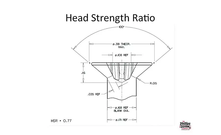
Now that we have agreed on the criteria to use for calculating HSR, it’s important to select whether the minimum or maximum of each dimensional variable should be used to determine the “worst case” scenario in which head-to-shank failure is most likely at tensile levels below those for the effective diameter of the thread pitch. We have already determined that for a fully threaded fastener, the cross-sectional area under the head is determined by the blank diameter, and that for a fastener with a full body, the larger body diameter will be used for the calculation. We should therefore use the minimum under-head diameter as the base line for the calculation.
Looking at Figure 2, it is easy to see that the maximum recess depth should be used as the base line for the calculation, since it yields the smallest cross-sectional area between the blank diameter and the nearest intersection with the recess. Typically, fully threaded fasteners are not used in critical applications, and in these circumstances it is often acceptable to allow an HSR that is less than 1 based on analysis of the application.
Influence of Recess Geometry
The last factor to consider when analyzing head strength at the head-to-shank juncture is the geometry of the recess drive system itself. Cruciform drive systems like Type 1 (Phillips), NAS33781 (Torq-Set) and Type 1A (Pozidriv) have a defined cruciform shape for most of the recess depth, from the top of the head to the bottom of the recess. In calculating HSR, we typically will ignore this shape and use a basic circular cross section based on the outer wing diameter at the closest intersection to the under-head transition radius for ease of calculation.
Straight-walled drive systems, like six-lobe (Torx) and others, have a constant outer shape from the top of the fastener head to the tapered bottom of the recess. In these cases, the distance from the head transition radius to the closest intersection with the recess shape is still used, except that the nearest intersection is often a circular area in the bottom of the recess, below the plane where the recess outer form has transitioned to a circular cross section.
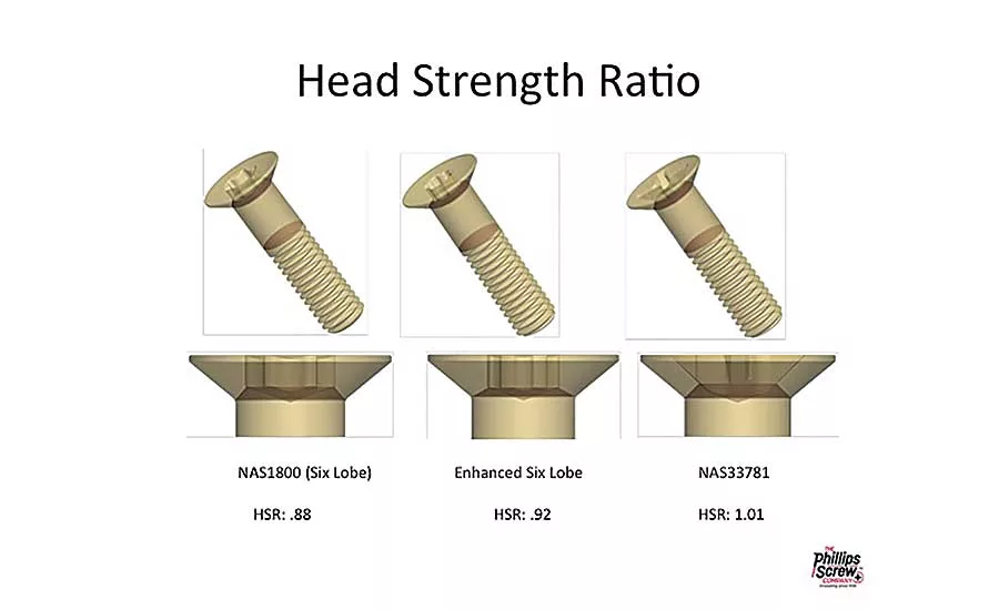
Fasteners with unthreaded shanks are typically used in higher stress structural applications, and in these situations an HSR of 1 or greater is recommended. Ideally, the maximum recess depth will be shallow enough to provide an HSR greater than 1, especially if the fastener is in an application that is deemed critical or semi-critical. While the configurations in Figure 3 show an HSR below or near 1 at maximum recess depth, if the parts are manufactured with the recess depth closer to the minimum allowed in the part standard, the HSR will increase as the recess depth approaches this minimum limit.
While we have used 100-degree countersunk aerospace fasteners for our discussion, the HSR should be evaluated for any other head configuration (pan head, fillister head, button head, etc.) during the initial design evaluation. While protruding heads like these will often have a higher HSR, the move to lighter weight and tighter tolerances has begun to require lower protruding head height designs and the recess depth may not always be considered when head height reductions are done to accommodate tighter clearances.
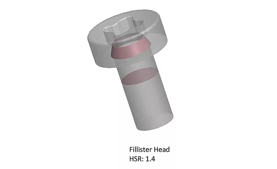
Higher head strength is achieved with protruding head configurations where the bottom of the recess has significant distance from the head-to-shank juncture, as in the Fillister head. (See Figure 4.) Increases in head strength can also be achieved in thin-head designs if a shallow recess can be used, such as AS6305 MORTORQ spiral drive or NAS33750 dovetail slot. (See Figure 5.) However, in a bolt application where significant torque is required, the drive system should have a very high contact area between the driver and recess to accommodate the high torque required to achieve the needed clamp load.
Looking for a reprint of this article?
From high-res PDFs to custom plaques, order your copy today!


