International Appliance Manufacturing
100 Shielding Tips and Tricks

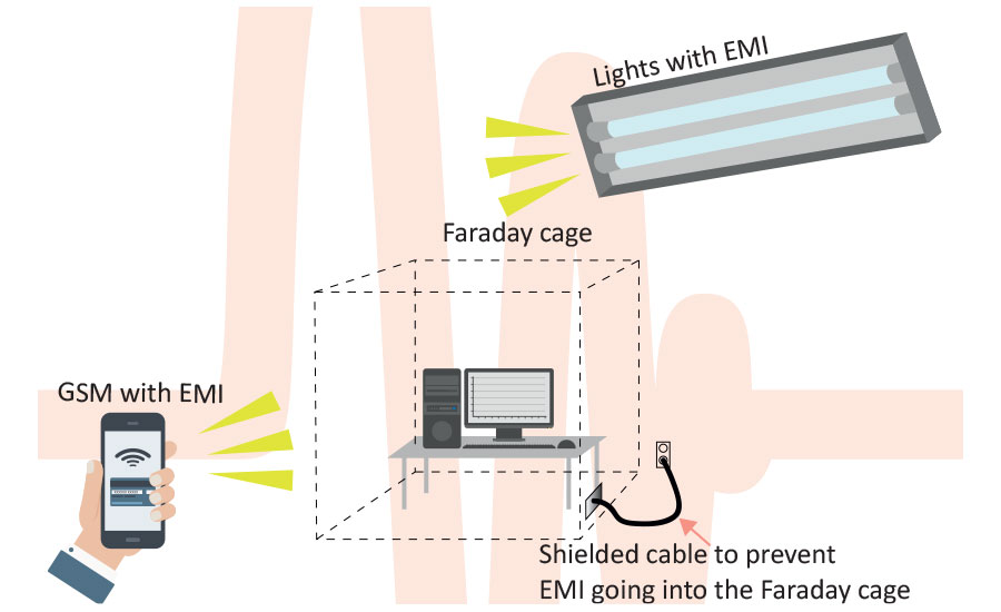
- The principle of shielding is creating a conductive layer completely surrounding the object you want to shield. This was invented by Michael Faraday and this system is known as a Faraday cage.
- Ideally, the shielding layer will be made up of conductive sheets or layers of metal that are connected by means of welding or soldering, without any interruptions. The shielding is perfect when there is no difference in conductivity between the used materials. When dealing with frequencies below 30 MHz, the metal thickness affects shielding effectiveness. We also offer a range of shielding methods for plastic enclosures. A complete absence of interruptions is not a realistic goal, since the Faraday cage will have to be opened from time to time so electronics, equipment or people can be moved in or out. Openings are also needed for displays, ventilation, cooling, power supply, signals etc.
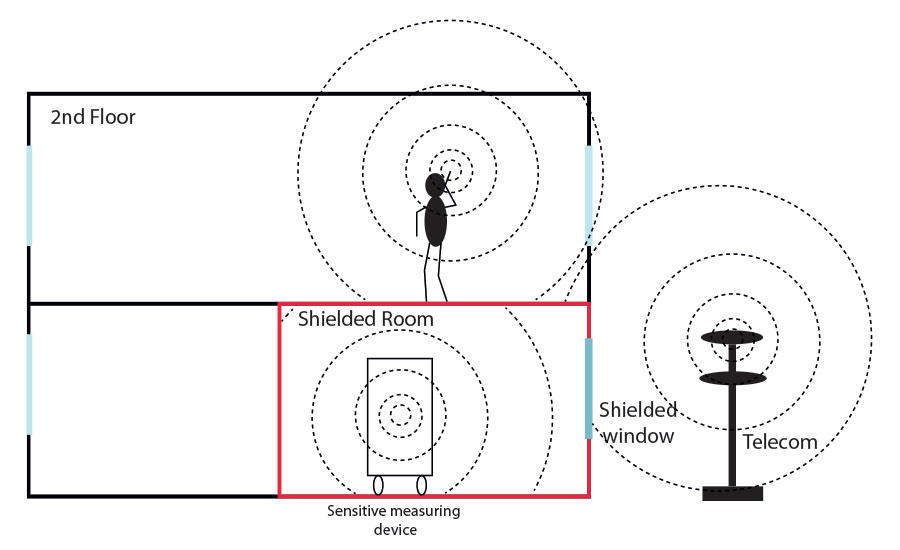
- Shielding works in both directions: items inside the shielded room are shielded from outside influences.
- The quality of the cage is expressed as the ratio of the field strength in Volts/meter (V/m) inside the cage and outside the cage.
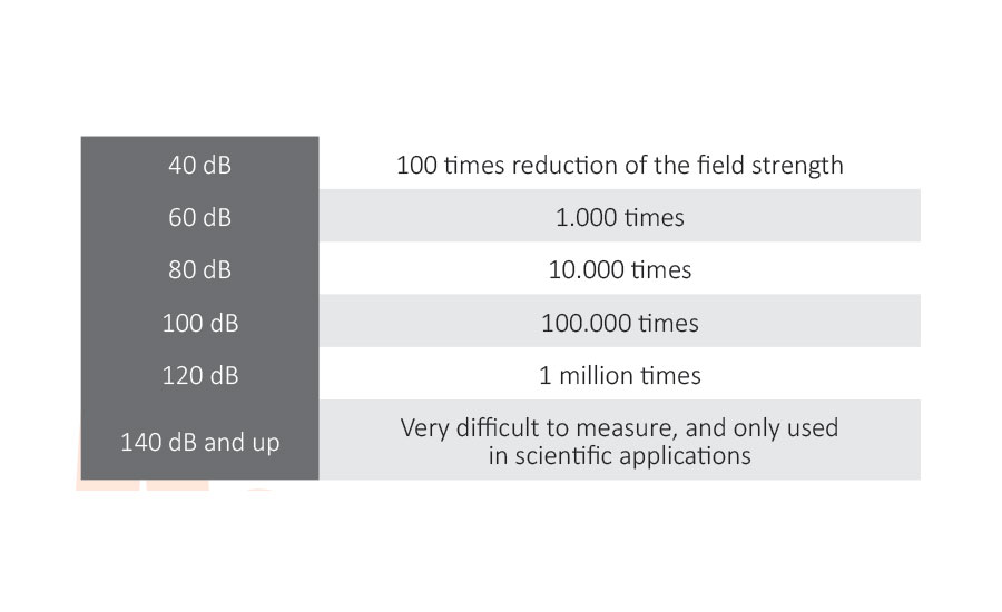
- It is common practice to present field strength figures in a logarithmic scale (in dB).
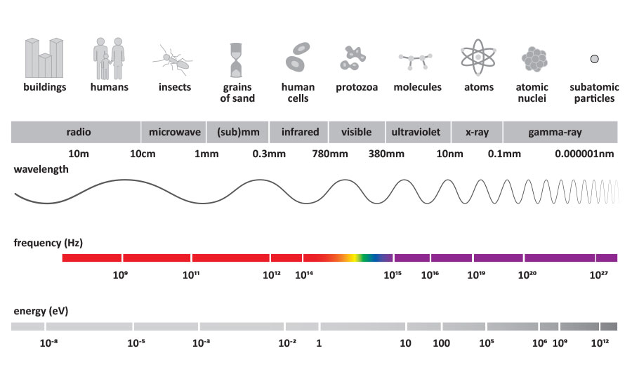
- The reduction depends on the frequency in Hz. Each frequency has a wavelength in meters.
For example 100 MHz = 100.000 Hz = 3 meter.
Waves
- A wave is a combination of electric field and magnetic fields. A electromagnetic wave is composed of a magnetic part depending on the electric current (ampere), and an electrical section, depending on the electrical voltage (volts). Near the source (near-field) the magnetic part is dominant. At a greater distance, the electrical part and the magnetic part are present in a fixed ratio (far field).
- The material thickness determines which frequencies are blocked from penetrating into or out of the cage. For low frequencies like 10 kHz (generally the near-field/magnetic fields), a mild steel layer of 6mm is needed to achieve a reduction of 80 dB, but a frequency of 30 MHz can be shielded by copper foil that is only 0.03mm thick. For higher frequencies in the GHz area the mechanical strength of the used shielding material will generally specify the thickness of the shield.
- For very low frequencies and DC where the magnetic field is dominant, besides thick layers also special materials like Mu-metal and Mu-ferro alloys are needed. In addition, combinations of multiple layers are required to get sufficient shielding performance.
- When a wire penetrates a shield that is not completely connected to the shield, it will work as an antenna and this reduce the shielding performance of the cage. This is especially the case at higher frequencies.
Why the Faraday cage principle for EMI shielding?
- Circumstances in which EMI shielding has to be implemented
- When a product has to meet government standards like CE or FCC which regulate immunity and compatibility of products.
- The regulations do not cover the requirements of daily practice
(e.g. medical instruments are tested at 3 meters distance while they are used within 15 cm). - Extra safety is desired for military use, e.g. for EMP (electromagnetic pulses).
- If someone wants to create increased levels of shielding for TEMPEST requirements, so that there is no risk of spying. Sensitive instruments or equipment are to be protected from interfering or harmful frequencies.
- Rules for sensitive measuring and weight equipment like balances and petrol-delivery materials have to be met.
- Other aspects related to shielding
- Regulations regarding ESD (electrostatic discharge).
- Regulations regarding ATEX (explosion safety).
- Lightning protection / EMP/ HEMP / NEMP.
- Short circuit protection / prevention of sparks.
- Identification systems like RFID (Radio Frequency Identification) prevent RFID from making contact with the stations.
Several frequency ranges, lower the frequency are for longer distances.
- 125 kHz (Low Frequency)
- 13.56 MHz (High Frequency)
- 860 to 950 MHz (Ultra High Frequency)
- 2.45 GHz (Microwave)
- Medical / personal protection: shielding certain frequencies can prevent illness caused by radiation levels. Protective clothing can reduce the field strength, depending on the density. To this end, there is personal protection in the form of clothing, hats, gloves, stockings, sleeping bags, tents and so on.
How to create optimal EMI shielding
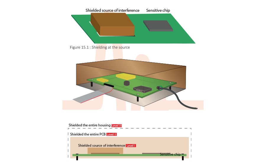
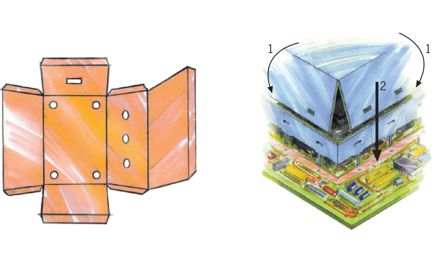
- In general, a shield consisting of more layers or zones is cheaper to produce than a shield made out of one high performance layer. It is easy to create three zones.
- Level I: The component on the PCB is shielded by a can. Shielding at the source.
- Level II: The entire PCB is shielded by foil, wraps or a box or the PCB and all the cables are connected inside the shielded box.
- Level III: Or the outer housing is shielded as well.
Shielding at the source
- Source
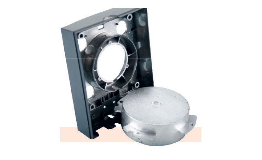
Shielding at the source is usually the most cost-effective solution. Generally speaking, the source of unwanted radiation can be produced by voltage and current through one or more components or interconnections on the PCB. Application of a shielding can will reduce it directly at the source.
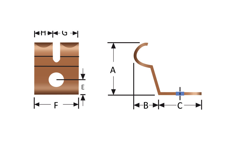
- Clip mounting
Shielding cans are mounted onto the PCB with SMD clips, which come in several sizes. After the re-flow, the can (a cover with walls attached) is placed into the clips and can subsequently be removed for adjustments.
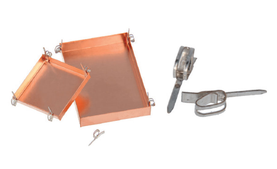
- Pin mounting
There are also systems with pins for though holes or covers with integrated pins that can be soldered directly onto the PCB.
- Shield layout
Cooling holes can be made in the cover or steps to prevent short circuits with the tracks on the PCB.
Looking for quick answers on assembly and manufacturing topics? Try Ask ASM, our new smart AI search tool. Ask ASM
- Covering the entire PCB
Another option is covering the entire PCB in shielding material. This can be achieved either by means of a small housing, custom-made to exactly the right shape, or by simply wrapping or sticking material around the PCB. Foils, textiles, stretch material, and wrap shields, cut to the appropriate shape, are easy to apply. Since it is always important to prevent short circuits, all materials can be provided with insulation layers.
Cable shielding
- Cables inside the housing
Once the PCB is covered, the attached cables can also be shielded. The longer a cable, the higher its potential for emitting lower frequencies. Shielding a wire inside the enclosure will also prevent cross-talk and will make the main enclosure act as a cavity, and thus amplify the radiation. To prevent this, the enclosure can be (partly) laminated with EM absorption material.
- For round and flat cables we produce shields in the shape of sleeves, wraps, tubes and textiles so that all type of cables can be shielded. Some cable shields need to be grounded at both ends, but it is usually best to ground at only one end to prevent common-mode currents.
Cable shielding
- The housings themselves, i.e. the rack, the box, the enclosure, the metallized box, and the Faraday cage, constitute the main cover of the entire system and also the connection to the outside world. Housings are equipped with displays, entries for power and signal lines, and cooling air-vents.
- Elements that can reduce the effectiveness of a Faraday cage

- Level |||A 26 32 Seams
- Level |||B 45 Doors
- Level |||C 10 63 69 Entries
- Level |||D 70 74 Transparent displays
- Level |||E 79 Ventilation panels
- Level |||F 64 69 Cables for power supply
- Level |||G 65 Cables for signals
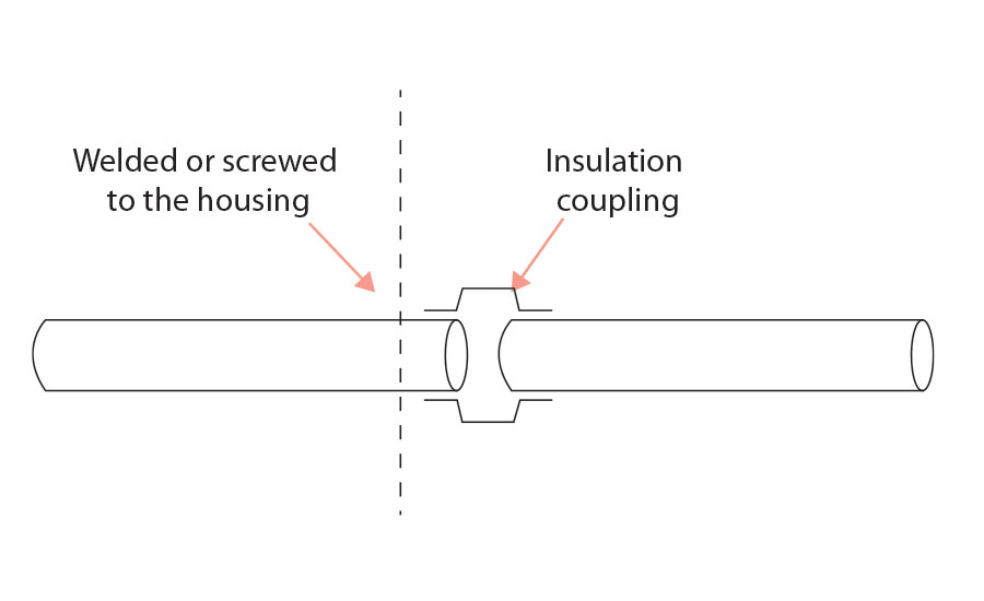
- Level |||H 64 69 Pipes for fluids, air, heating
- Level |||U 64 69 Cables for optical connection
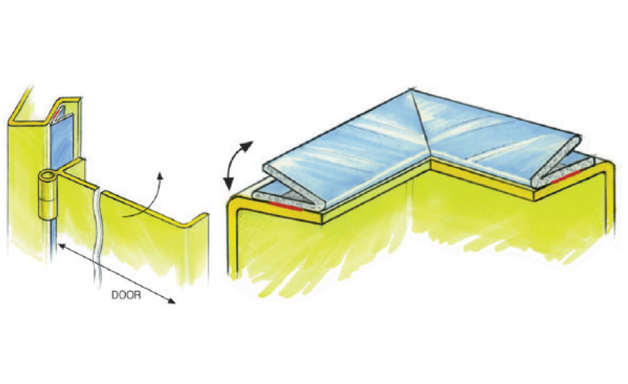
Seams
- It is important for the conductivity of the seam to be more or less identical to that of the basic material that the cage is constructed out of. Welding or soldering tends to works best, but for places that have to be opened easily several mechanical connection methods are available: clamping, screwing, adhesive, sealing, sticking.
- Characteristics of an optimal seam
- It is flat and smooth
- It has the right dimensions
- The construction is stiff enough
- It is and will remain free of corrosion
- If possible, it is in a single plane
- A superior flat surface can be achieved by machining and finally grinding the top surface. This is an expensive process and requires a stiff construction.
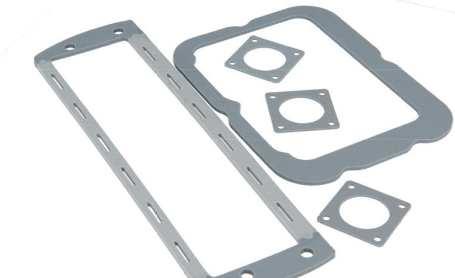
- To reduce cost, the connection can be improved by using a conductive gasket, which will fill in any gaps. A gasket can also be used to seal against water or to meet other IP demands.
- The softer the gasket, the more tolerance can be compensated and the lighter the eventual construction will be.
- If more tolerance is allowed, a less accurate production method can be used and production becomes more cost-effective.
- A lighter construction can also be effected by having smaller distances between the fixings: this results in more hinges, more locks, and more bolts. All of these extra elements result in higher cost and longer mounting and demounting times.
- Right dimension. It is possible to integrate an IP sealing with the EMI gasket. The IP gasket on the “water side” protects the EMI gasket against corrosion.
Prevention of corrosion
- In the design stage it is important to specify the environment.
It makes a difference whether the construction has to be able to withstand only humidity, or exposure to water (possibly even salt water), fog, or condensation, e.g. during transport. - If the metal of the housing is sensitive to corrosion, a finishing of e.g. nickel and chrome can help the contact surface maintain the required conductivity. Materials like aluminium and zinc-plated steel develop an oxidation layer, which reduces the corrosion process but is less conductive.
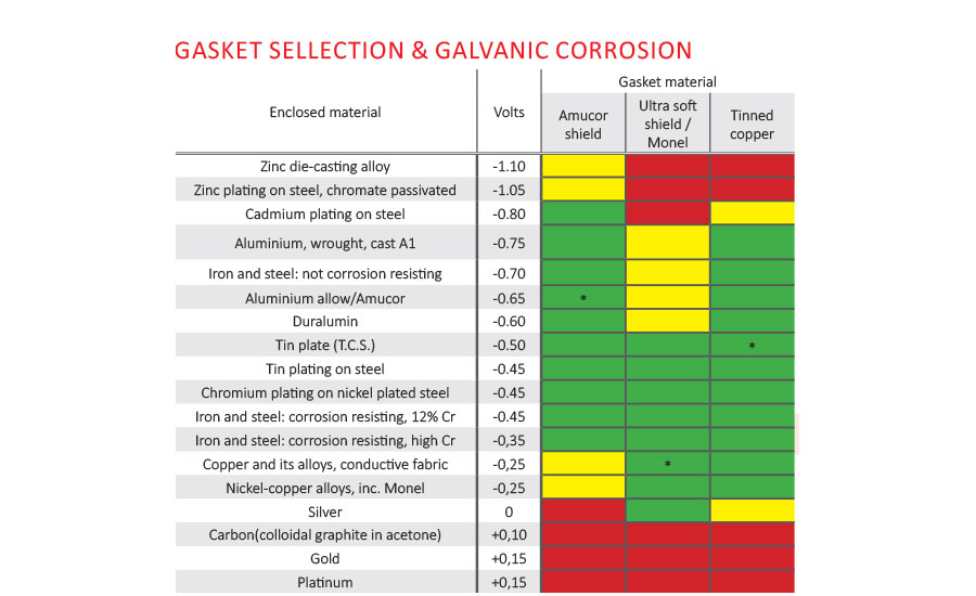
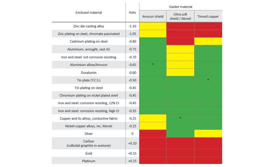
- Gasket selection & galvanic corrosion. Even when the materials of the housing withstand corrosion well, it is important that they work together not only with one another but also with the gasket
- Sea/water environment: In a situation where the galvanic values of the gasket and the housing material differ more than 0.3 volts in a salty environment, or 0.5 volts in an environment with just water, galvanic corrosion will occur. Even at a distance of 10 km from the sea, the atmosphere may be as salty as right on the coast. So the appropriate gasket material has to be chosen.
- Around the bolt holes should be sufficient space for a water seal.
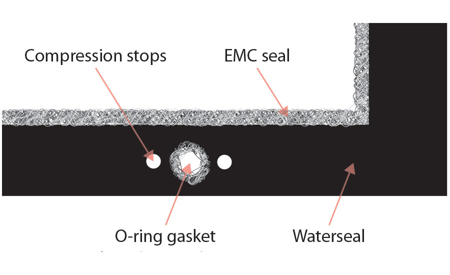
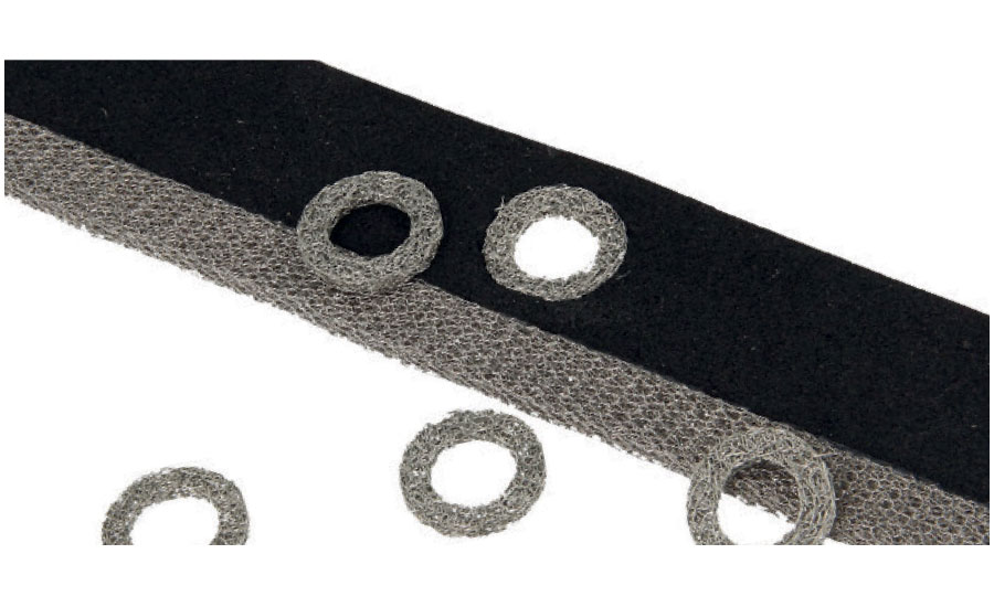
Water should never reach the EMI gasket or the construction via the bolt holes. Alternatively extra water sealing can be applied around the bolts in the form of rings.
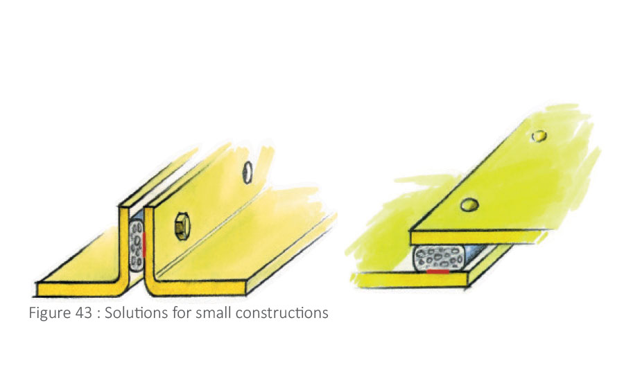
- For small parts, where there is less space a gasket out of electrically conductive rubber can be used. These are available in profiles and plates, which can be cut accurately to the required dimensions.
- For bigger parts it can be more efficient to use a combined gasket. An EMI gasket with a water seal made of neoprene, silicone or EPDM rubber.
- Neoprene has quite good flame retardant properties and can handle temperatures of -40 to +100 C. EPDM rubber can withstand temperatures up to 120 degrees, making it suitable for the engine compartment of cars. Silicone rubber is used for temperatures up to 220 C; it can be sterilized for medical applications and is soft. The rubbers can either be made in the shape of a foam or mousse or as a solid product.
Rules of thumb for gasket choice, depending on the type of enclosure
- Very small construction: (smaller than 150 x 150) grooves, casted, molded or machined: conductive profiles, o-ring or cut gasket out of highly conductive rubber are suitable.
- Small construction: (about 200 x 200mm) multi-shield gasket, consisting of metal wire from top to bottom though a soft silicone rubber with a thickness of 2 to 3 mm are suitable.
- Medium size construction: zinc-plated steel/metal: standard shield, neoprene foam with water seal, minimum width about 4 mm and thickness 2 to 3 mm.
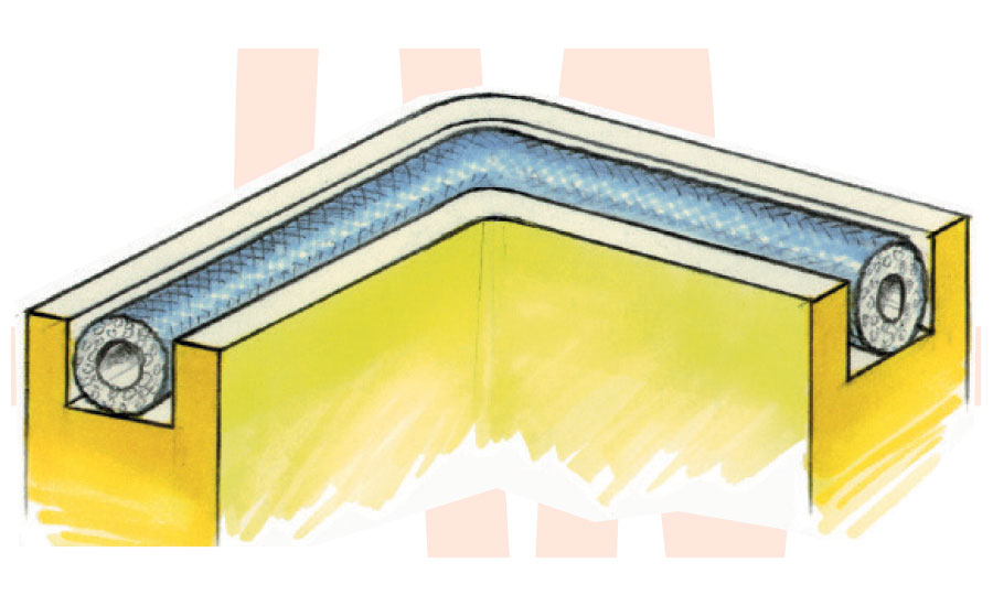
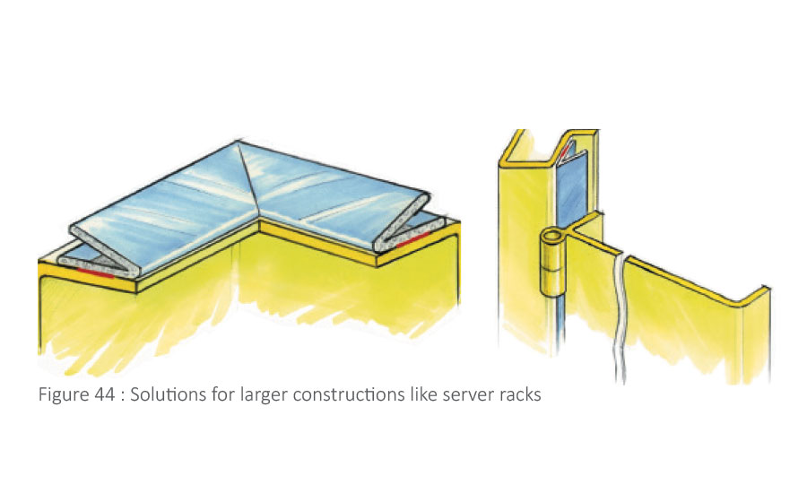
- Full size rack with door: Ultra-soft twin shield with separate water seal or knitted mesh over silicone tube with water seal, V-shape with additional water sealing, thickness 6 to 10 mm are suitable. Other products like finger strips, textile-covered parts, clip-on gaskets or custom build hybrid gaskets are suitable.
Shielded Doors
- The closing force of a shielded door/Faraday cage door should be reduced as much as possible so that it can be opened by hands. For more information read #54.
- Gasket thickness: Ultra-soft gaskets will help limit the closing force as well as bending of the door.
- Just as indication, at a server cabinet of 600 x 2500mm, a gasket of 6 mm thick may be used and an electronics housing 200x600 mm a gasket of 6 x 4 mm is an optimal size. In order for a gasket to have sufficient stability, its width should exceed its height.
- In the case of a screwed connection at a housing, entry panels, windows, or vent panels, the closing force is less important. Depending on the plate thickness and bolt distance, 1 to 2 mm is common and Amucor shield is a very good choice for the materials used most often.
- When the housing has only one edge flange while a water and EMI seal are needed, this can be created by using clip-on gaskets. Of these gaskets more than 200 different shapes have been produced edged with mesh or highly conductive textiles. They are mounted by means of clamping. When we cut them into shape according to the customer’s wishes, they can even make angles of 90 degrees.
- For instruments and introducing high currents into a construction we make over 2400 different Be-Cu finger strips. These are not allowed in every country and are susceptible to being damaged when they are used in a construction that is not protected properly (knife-edge).
- Gaskets can be made in the shape of a frame, complete with mounting holes and self-adhesive strip for mounting, if desired.
- In order to keep a gasket from becoming overly compressed, it is possible to add compression stops next to the bolt holes. If there is enough space, plastic or metal rings (compression stops) with the final thickness can be integrated in the gasket.
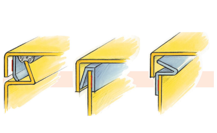
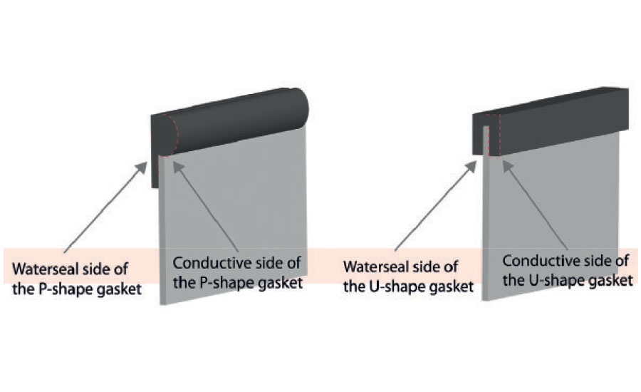
- For easy mounting there are gaskets in a P-shape or U-shape available. These gaskets can be easily mounted on a rim due to their shape.
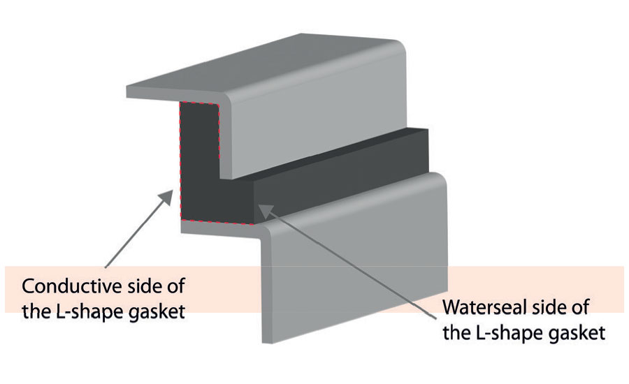
- L-shaped gasket can be used in constructions where EMI with water sealing is required and when there is just one flange. Maximum compression is 30%.
- To prevent high closure force V-shaped gaskets can be used which clamp the door not in the direction of the opening but in the direction of the door, so only the friction force is the closing force.
- For special constructions our custom-built profiles can help to create an optimal seal.
- Watertight EMI gaskets in any shape can be cut out of sheets of material like conductive rubber, or multi-shield with small conductive wires in the material. They have a compression of 10-15%.
- Conductive foam is an open structure so it is not watertight, but it can be combined with a watertight neoprene gasket.
- Knitted mesh for military and low-frequency use is available made out of full metal (10-15 % compression) neoprene foam covered with knitted metal wires which has 30-40 % compression. Silicone tube covered with knitting has up to 50% compression and low compression force.
- The knitted-mesh gasket can be mounted into a groove or can be produced with a fin so that it can be screwed or clamped.
- When there is no groove in your construction the knitted wire mesh gasket can be glued to self-adhesive rubber, to keep it in place.
- For high-performance gaskets to seal gaps in for example Faraday cages for sensitive measurement the gaskets can be produced in a double implementation and bolted in the center.
Cable shielding
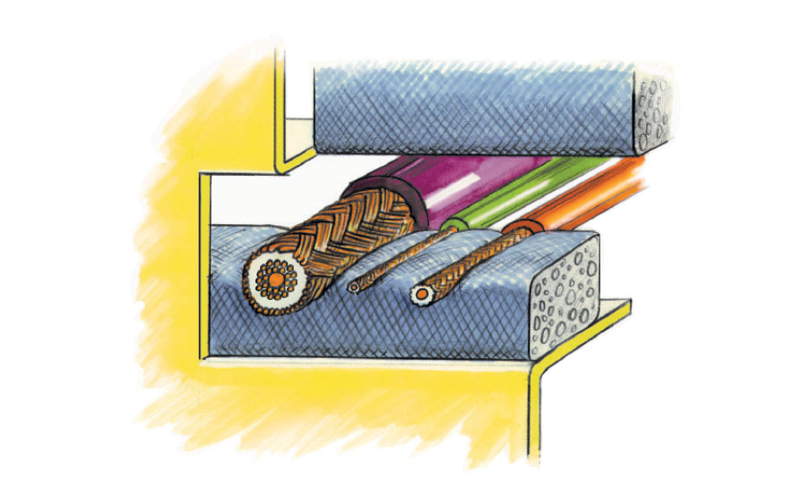
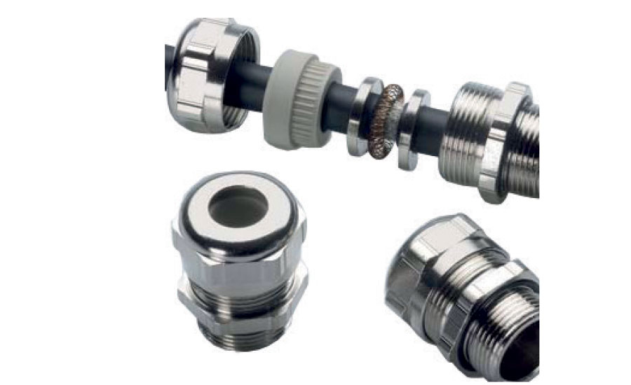
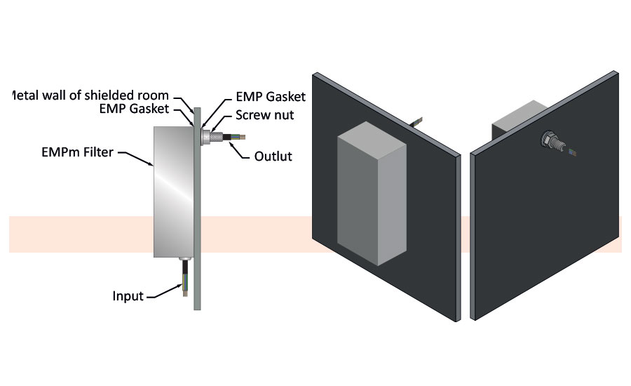
- Cables entering a Faraday cage can carry undesirable signals into and out of the housing. When these cables are shielded, the cable shield should be 360 degrees around the cable, and be connected to the housing using a gland or cable entry plate. Entry shielding is also available in watertight and flame retardant versions. Power lines and signal lines should be filtered when it is not certain what frequencies are on the line.
- Filters for power, signals and data. A power line coming from the grid function as an antenna of immense length and brings many unwanted frequencies with it. It has to be “cleaned” by a filter before entering the shielded room. The same goes for signal lines and pipes going into the housing. They will work as an antenna and interfere with the shielding.
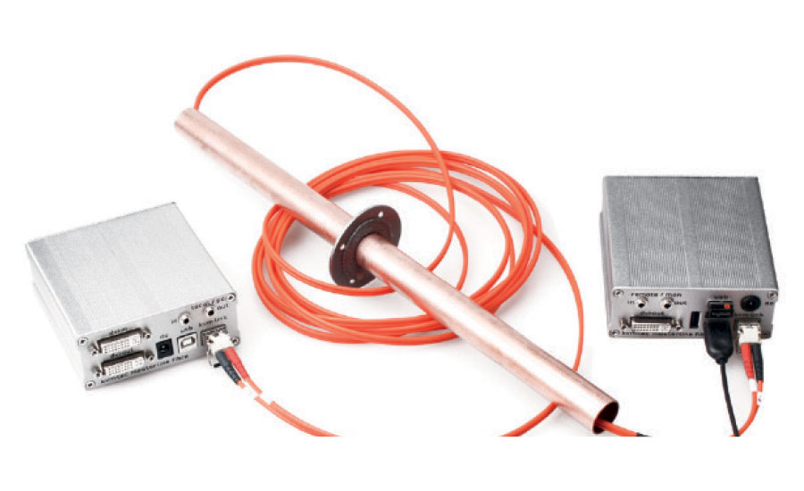
- Shielding for data lines is done by converting the signal to light and bringing the signal into the shielded room via a fiber optic cable through a waveguide. The fiber optic cable is nonconductive and will not bring in unwanted signals.
- A power- or signal line filter should be grounded to the Faraday cage so that there is a connection with a low impedance to the body of the shield. This is needed for discharging unwanted signals.
- It is best to position all filters close together but to separate the signal line filters away from the power line filters to prevent currents through the cage wall from the power line filters interfering with the signal line filters.
- The shielded housing creates a new “ground” and should be connected to the common ground of the building, only for safety reasons. This is to prevent voltage on the cage in respect to the earth.
- When you want to enter a clean ground line inside the cage, other than the earth line of the housing you also need a ground line filter for this extra clean ground line.
Displays
- Products for transparent shielding
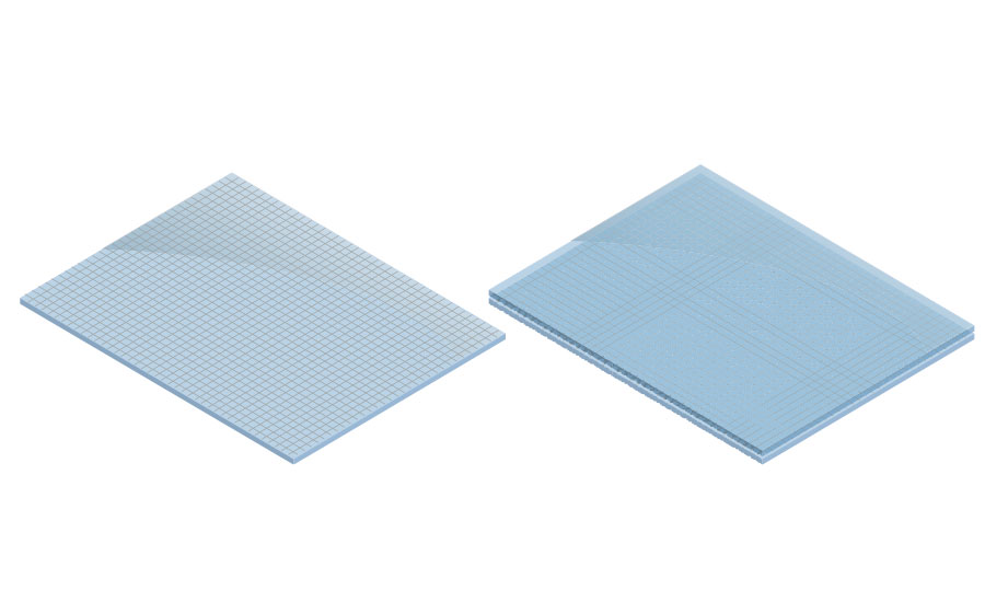
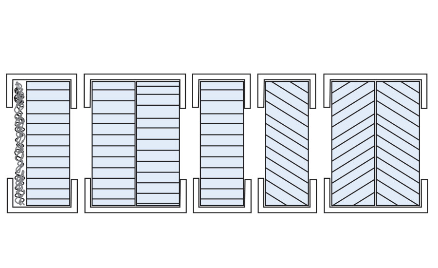
- Woven mesh 73
- Woven mesh between sheets of acrylic, polycarbonate or glass, connected at the edges (edge bonded) 73
- Woven mesh, fully laminated between plates of acrylic, polycarbonate or glass 73
- Woven mesh between foil with or without self-adhesive 73
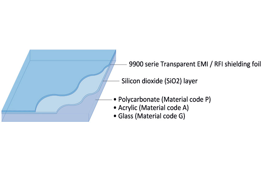
- Indium tin oxide (ITO) on foil or glass, 4 or 6mm (transparent foil)
- Copper grid on foil, high light transmission versus shielding performance 74
- High performance combinations of above materials, framed in metal with gaskets for easy mounting 75
- Transparent foil with anti-static layer (ESD foil)
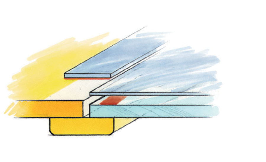
- Mounting a transparent window. In order to ensure good shielding performance a transparent conductive shield can be provided with a silver contact busbar. Some shields can be made with flying mesh so that the flying mesh can be connected to the shielded housing. The shielded window should make full contact with the housing on all its sides by means of conductive adhesives, conductive seals, tape with conductive adhesive, or clamping with a gasket if desired.
- Conductive foils can be stuck to a standard screen or window with cleanly removable self-adhesive. More rigid transparent shields can be made with a frame or mounted with a bezel.
Warning
It is currently not possible to make transparent shields 100% optically correct because of the so called moiré effect, so minor disturbances have to be accepted.
Choice of transparent material
- Mesh foil. For shielding at low frequencies, mesh shielding types show the best performance. They have lower light transmission than for example ITO coated windows and foils but that is considered normal for a display rather than a problem. When the foil is applied to a monitor and the lines of the mesh in the film do not correspond with the dots of the monitor a Newton’s ring effect or a moiré pattern will arise. Orienting the mesh at a certain angle between 17 and 45 degrees will minimize this effect. Please note: there is a physical rule: the finer the mesh, the darker the material, the better the shielding performance.
- ITO Coating. Indium tin oxide coating does not produce a moiré effect and offers good shielding at higher frequencies. The product is however sensitive to acid substances, such as for instance found in finger prints. Optionally a plastic film layer may be applied in order to protect the ITO layer.
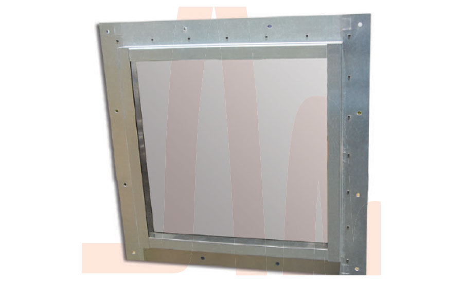
- Framed windows. We produce turnkey shielded windows with up-to and even over 100 dB attenuation that can be installed directly into an MRI room. These windows are framed and have several layers of shielding, all of which are connected to one another.
Shielding methods for plastic housing
- It is possible to apply a shielding foil inside the housing, either completely or partially glued to the housing. With the use of stiffer foils a shielded box can be created inside the plastic housing in cases where there is no need to have the housing fit a specific shape. Lips on the precut foil can be used for grounding and/or mounting.
- For housings with complex shapes, a shielding paint or spray (in cans) can be used. The paint is filled with conductive metal particles like nickel, copper, silver or combinations.
- Metallization under vacuum (sputtering) is another option; this can also be done partially. Since a jig is needed for this process, it is not recommended for small production amounts.
- Parts can be subjected to galvanic treatment when dealing with larger quantities.
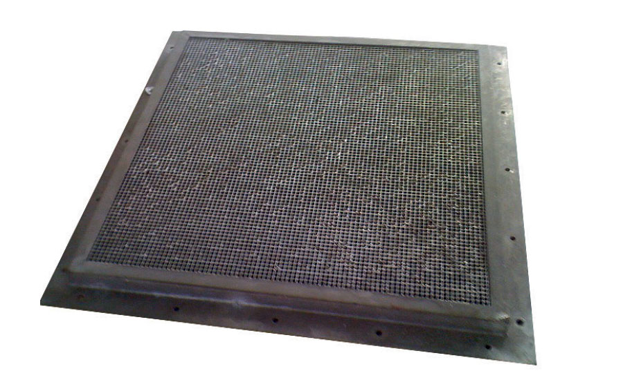
Ventilation panels
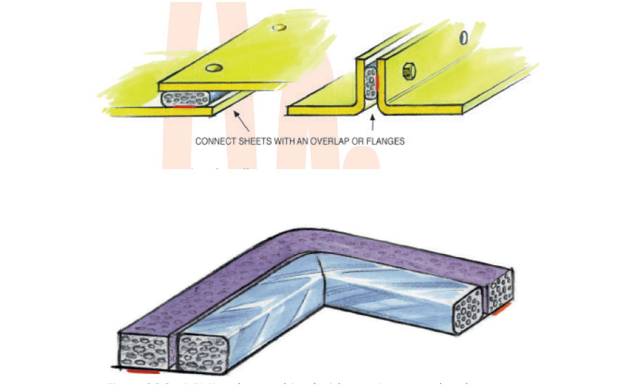
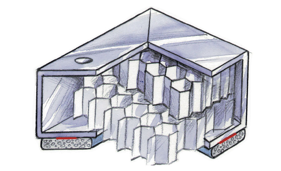
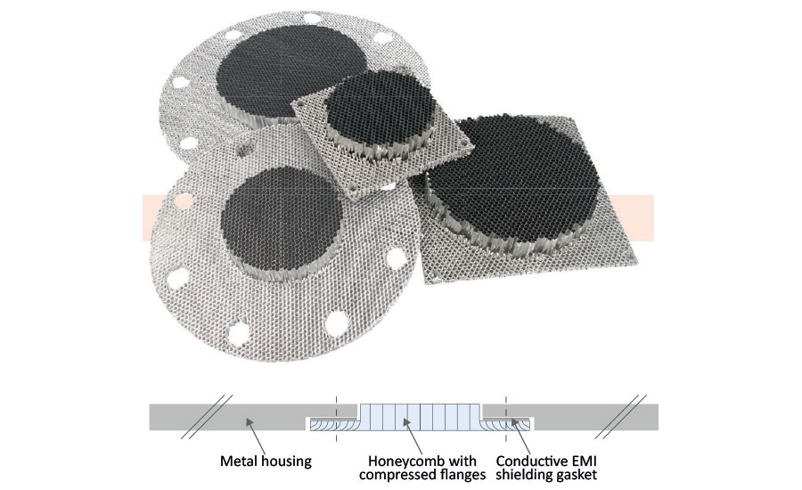
- Within a few days we can produce Honeycomb ventilation panels according to the customer’s drawing. The honeycomb structure is like waveguides and lets air though while blocking electromagnetic waves from entering.
The cell size of the honeycombs is 3.2 mm and combinations of sever layers is possible, even under cross constructions for higher performance. A cross cell honeycomb consists of minimal two layers of Honeycomb material stepped and rotated 90 degrees relative to each other. This results in a good shielding performance independent of the polarization of the waves.
- To prevent from dust, a dust filter can be integrated in the ventilation panel. The dust filter can also be mounted to the outside of the enclosure.
- The standard cost-effective honeycomb is made of aluminum but for special applications like EMP it can also be made out of mild steel, which is more expensive.
- A honeycomb ventilation panel can be framed and pre-drilled on request for easy mounting or can be produced frameless with optional a pressed flange for smaller constructions or when the honeycomb ventilation panel is mounted in a clamped construction.
- For outdoor use the honeycomb can be treated with a nickel or other finish. This is to protect the honeycomb ventilation panel from environmental influences such as corrosion.
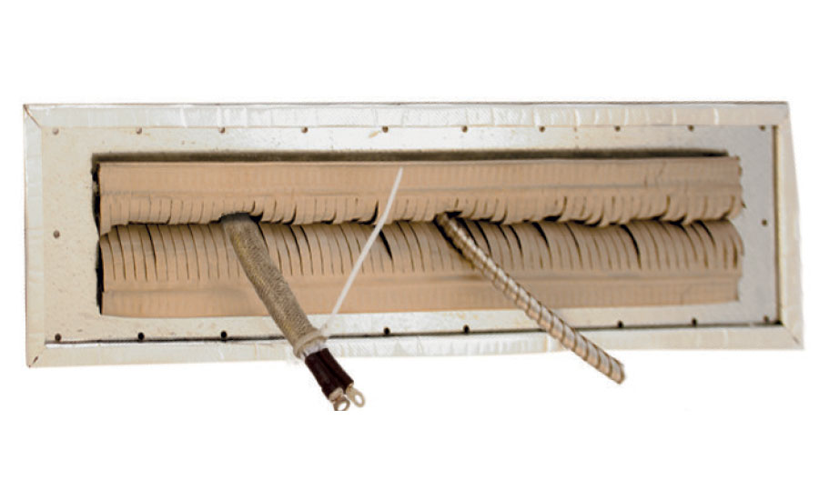
- To keep raindrops from falling into the enclosure we can make the honeycomb also at a slant (45 degrees is standard)
- Two layers of slanted honeycomb placed opposite to one another also make it impossible for metal rods to be entered into the cage, and thus prevent from electrocution.
- Mounting framed honeycombs can be done via through holes or threaded holes which are flow drilled into the frame in order to achieve a good screw length. Flow drilling is better than using rivets which may become loosened.
- Honeycombs can also be used as flow straighteners since the structure of the honeycomb material ensures that air is blown in a fixed direction.
- The honeycombs can optionally be provided with a flange so that the honeycomb after mounting forms one whole shape with the shielded enclosure.
Cables
- Cables from and to a shielded enclosure should also be shielded when no sufficient entry like power line filters are used.
- Optimal cable shielding can be achieved with several materials like conductive flexible shielding tubes, wraps made of knitted metal, highly conductivity textiles or foils. All these materials can be supplied with- or without self-adhesive
- The cable shield should be low impedance connected at the entrance of the screen, wall or body of the shielded enclosure. That way there is not only a galvanic connection but this also creates a high frequency coupling. A full 360-degrees connection around the cable works best. For this purpose we produce cable entries.
- Inside the enclosure cables can emit radiation which can then be amplified by the cavity of the enclosure, so it may be important to also shield the cables inside the enclosure. Tie-wraps and compressible cable-clamping strips can be helpful to make good connections with the conductive metal connector of the cable.
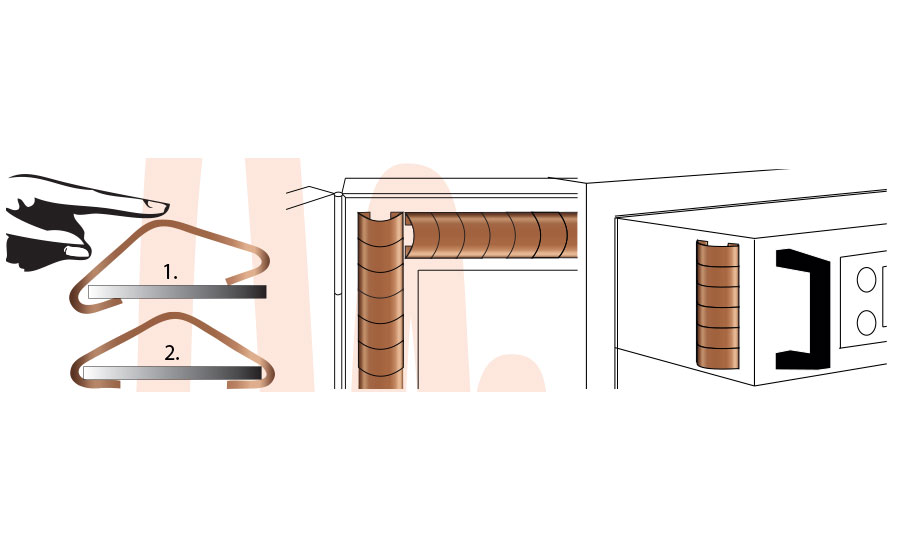
Fingerstrips
- To pass on higher currents for entry plates and so on, a very good product are beryllium copper fingerstrips. Please note that not all countries accept these due to the percentage of beryllium which is toxic, therefore we have developed many other types of conductive gaskets which are more friendly for the environment and also less sensitive for damaging. Also a good solution is to place knit mesh between the entry panel and the cage wall.
- For screwed connections the 2400 series twisted fingerstrips are very popular. They can be compressed to the fingerstrips material thickness like 0.25 mm. Most versions can be stuck with a self-adhesive strip to keep the strip in place.
- For shielded doors and Faraday cage doors you need a bigger range of compression. You find these in the 2800 series fingers can be clamped, soldered or screwed.
- The 2100 series clip-on mounting Fingerstrips can be clamped on regular metal plate thicknesses like 0.5, 0.8, 1 and 1.5 mm. Some even have lances so that the strip will not slip loose quickly.
- When there is a wide range of compression required, the 2200 series Snap-on Fingerstrips or 2300 series Stick-on fingerstrips may be suitable. These fingerstrips with self-adhesive can be integrated in the construction. Snap-on Fingerstrips can be firmly mounted in slots in your construction so that also a compression to nearly 0.25 can be realized.
- For special constructions the 2500 series show fingers mounted under an 90 degree angle.
- For circular mounting the fingers in the 2600 series have on top of the finger spherical tips so that there is under any angle a good point contact.
- For sliding, rotating and moving applications, please contact our specialists. To prevent wear down there is a conductive lubricant available.
Looking for a reprint of this article?
From high-res PDFs to custom plaques, order your copy today!


