Options for Tinning Wire
Whether applied manually or by a machine, the tinning process improves the mechanical strength of bare copper wire
Like any assembly skill, manual soldering of wire can be learned through proper training. This training begins by teaching the person how to cleanly strip, tin and solder the wire to a connector, PCB or terminal.
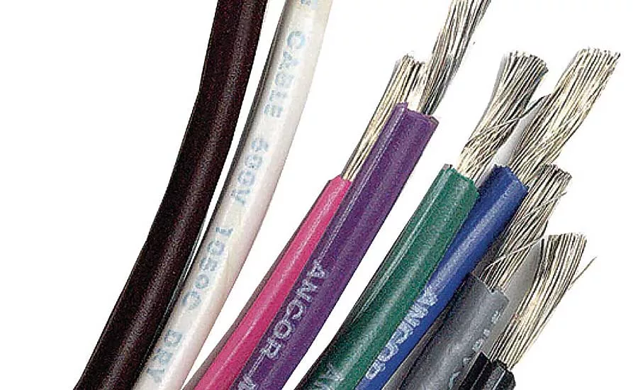
Tinning wire is an essential part of soldering preparation. When done properly, it improves the operating temperature range, water resistance and mechanical strength of bare copper wire. It also prevents conductor strands from fraying when connecting a stripped wire to a termination site.
Manual tinning is a simple three-step process. After gently twisting together all the conductor strands, the worker apples a thin layer of flux to the strands and then a thin layer of solder compound.
This compound contains tin-lead or is lead-free (tin-silver-copper) and may be applied by dipping the wire end in a heated solder pot (700 to 800 F) or using spooled solder wire in conjunction with a hot solder iron. After tinning, the treated wire end is silver in color, and smooth and uniform in appearance. It quickly dries and is then soldered in place.
“At many wire-processing facilities, manual wire tinning is quite common,” says Rob Boyd, senior product manager at Schleuniger Inc. “You’ll see workers regularly dipping wire into solder pots to do the tinning.”
The practice of tinning wire has been around for as long as people have manually performed soldering. The reason is simple: Tinned wire improves soldering connection between wire and terminal.
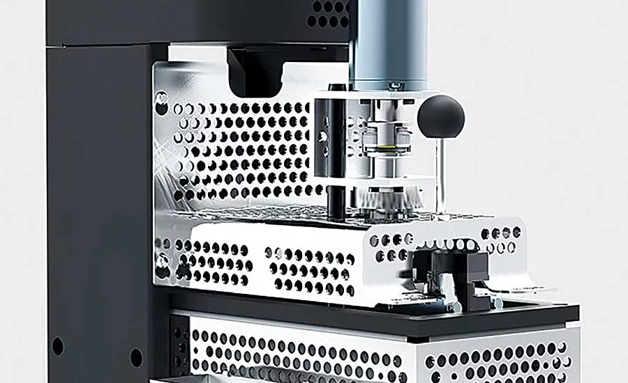
In recent years, suppliers have developed equipment that automatically tins wire. One automated machine can even be equipped with a monitoring device that uses a camera to inspect the tinned wire area and verify if it’s within tolerance. Which method is best for an application depends on factors like production volume, wire size, available floor space and budget.
Looking for quick answers on assembly and manufacturing topics? Try Ask ASM, our new smart AI search tool. Ask ASM
A Quick Primer
Initially, tinning was used to protect the copper conductor from corrosion due to chemically reacting with the sulfur ions in the wiring insulation. Modern chemistry has since created more stable wiring insulation, and tinning is usually not required just to prevent corrosion from within.
The exception to this rule is sulfur-bearing power-cable insulation, which is made of chlorosulfonated polyethylene and still requires tinning to protect copper wire from sulfur-caused corrosion. Other corrosive and harsh environments where tinning effectively protects copper conductors are marine and industrial facilities such as water and pulp treatment operations.
Research shows that tinned conductors have a wire life nearly 10 times longer than bare wire, and that tinning a wire does improve its solderability initially. Over time, however, the migration of tin and copper, and tin oxidation can degrade the tinning’s solderability and conductivity.
Another benefit of tinning is material affordability. Tin-lead and tin-silver-copper alloys cost much less than nickel and silver.
In addition, tinned wire produces a soldered joint with better thermal and electrical capabilities than when done on bare copper. This is especially important when soldering wires to D-Sub electrical, circular and other military connectors, or joining two tinned wire ends or one wire end to the middle exposed area of another wire.
Another common application involves soldering the tinned ends of one or more wires to specified termination sites. The challenge is making sure to not disrupt the other end of each wire, which is either crimped to a terminal or encased and overmolded into a connector.
Leaded and lead-free solder compounds are still used for tinning, although most industries require the use of lead-free material, per OSHA standards. One exception is the aerospace industry. Aerospace manufacturers mandate the use of leaded solder because lead-free solder often forms whisker-like projections in assembled parts that sit dormant or in storage for extended periods of time.
It is important to point out that crimped terminations of tinned wire has been and remains an area of dispute. Both the IPC-J-STD-001 Rev E section 5.1.3 and IPC/WHMA-A-620 Section 4.4. standards recommend that tinned wire not be used in crimp terminations, under screws (such as in terminal blocks) or when forming mesh splices. The reasoning behind these standards is that downward pressure from the crimp, screw or splice will break the solder joint. This, in turn, can leave an opening within the strands, which then become susceptible to vibration, loosening and corrosion. Untinned wire also provides a better gas tight joint.
“Although it’s not standard practice, some manufacturers do crimp tinned wire in terminals,” says Erich Moeri, technical sales engineering manager at Komax Corp. “The main problem with this is the solder skews the data obtained during crimp force monitoring. The monitor seeks clear copper contact in the terminal, but the tinning prevents the monitor from accurately determining if the crimp is good or bad.”
Manual or Automated
Manual and automated tinning processes have specific advantages and drawbacks. The manual approach is simple, but only practical for
low-volume production. This is because quality and accuracy can vary from worker to worker—and even by the same worker from the start to the end of his or her shift.
Automated wire tinning is more complex and expensive, but it ensures repeatable and uniform coverage on large amounts of wires. Boyd says that all wires tinned on automated equipment are immediately ready for soldering to a termination site.
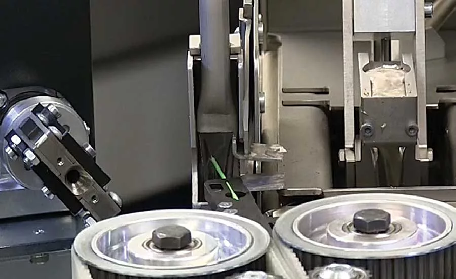
Introduced more than 30 years ago, automated tinning machines feature pumps that pump flux and solder at separate locations in a downwardly flowing stream. A built-in gripper grips the wire and moves it into both stations sequentially to leave a coating of solder on the wire.
From the early 1990s to the early 2000s, Komax produced custom automated tinning stations for customers on demand. Then in 2003, the company introduced its IOC785 electric module as an option for automated cut-strip-and-crimp machines. The module is located after the wire stripping function.
The operator turns on the unit so its tin container warms up. After closing the module’s safety shield, the unit’s variable speed pump produces a steady flow of solder compound that flows downward into a reservoir.
Tinning occurs within a few seconds, and involves preprogrammed grippers grabbing a wire, quickly swiveling its stripped end through the flux container, and then quickly passing the wire end through the flowing solder.
The pump’s adjustable speed and precise temperature control ensures repeatable and high quality tinning of all stranded wires. Equally beneficial is a specially designed pump channel, which optimizes solder flow so there is minimal slag formation. The module also allows for the use of lead-free tin to limit component wear, features quick-change fittings for fast and efficient setup, and can be dismantled without tools. The latter benefit dramatically reduces cleaning time.
In 2017, Komax introduced the X1585 fluxing-tinning module, which offers versatile lead-free tinning of strand ends. The module comes with a variety of tinning nozzles to cover a broad spectrum of applications. Each nozzle can be disassembled during operation.
The fluxing station is compact and integrated as standard, while the solder container is easily accessible on any fully automatic wire processing machine. According to Moeri, the X1585 functions best when combined with the company’s X1582 strand-twisting module. He says that twisted strand ends increase tinning accuracy.
Schleuniger introduced its first fluxing-tinning module, the STS 1000, in 2006. An upgraded version, the STS 1100, was brought to market in 2012 primarily to help end-users accommodate the ROHS standard that requires the use of lead-free solder for tinning applications. The STS 1100, like its predecessor, allows the operator to program all fluxing and tinning parameters.
According to Boyd, the STS 1100 quickly performs fluxing and tinning of stripped wire ends (stranded conductor or coax) with a cross section up to 14 AWG and a tinning length up to 0.2 inch. Optional equipment enables the module to process up to 12 AWG wire and a tinning length up to 0.39 inch. In addition, this module can be used with the company’s STW 1100 strand-twisting machine.
“The upgraded version lets operators exactly program how fast and how far the stripped wire end goes into and comes out of the flux spout and solder waterfall,” notes Boyd. “The spout and waterfall are mounted side by side, only two inches apart.”
Short cycle time is a key benefit of the STS 1100. Boyd says that 14 or 12 AWG wire can be processed at a speed of 1,200 pieces per hour. Smaller wire can be processed at a speed up to 2,000 pieces per hour. However, the actual rate will depend on the application.
“Maintenance is the biggest challenge with automated fluxing-tinning machines,” says Boyd. “Quite often, operators use the fastest possible settings to maximize machine output. This results in sticky flux and solder that has not fully solidified on the wire being thrown around the machine. Therefore, maintenance efforts to keep the machine clean need to be increased.”
Moeri says that some manufacturers use the X1585 in conjunction with the company’s X1240 strip monitor, which comes with a camera. Each wire passes by the camera, which quickly inspects the tinned area to verify if it’s within tolerance.
“If not, an integrated ‘cut up bad part’ function automatically recuts the wire end about 10 or 15 millimeters before reprocessing and re-tinning it,” explains Moeri. “The monitor then informs the operator how many wires were cut and left alone per batch. In addition, the operator can program the monitor to notify him if successive bad wires appear so he can stop and inspect the equipment.”
Looking for a reprint of this article?
From high-res PDFs to custom plaques, order your copy today!


