Double-Sided Self-Pierce Riveting

For light weight and good conduction of heat and electricity, bus bars are made of copper, aluminum or a combination of the two. Photo courtesy EMS Industrial and Service Co.
If the battery pack is the heart of an electric vehicle, then the bus bar is the aorta, conducting electrical current to the motors and other systems. For light weight and good conduction of heat and electricity, bus bars are made of copper, aluminum or a combination of the two.
Joining these dissimilar materials has posed a challenge. Soldered butt joints are one option, but defects can result from various metallurgic alterations produced during fabrication. Laser welded lap joints are another option, but it’s expensive.
We propose a third alternative: a half-lap joint produced via double-sided self-pierce riveting (DSSPR). This technique combines the advantages of lap and butt joints. Like a lap joint, it maximizes the contact area between the mating parts. And, like a butt joint, it creates seamless upper and lower surfaces without protrusions.
In DSSPR, a double-sided tubular rivet produces a mechanical joint between two sheets. The rivet has a simple geometry and remains hidden between the sheets. There is no deformation or exposed head on either side. A tubular rivet with chamfered ends penetrates the sheets as they are compressed against each other. This deformation increases the strain hardening of the sheets, which forces the rivet ends to flare, creating a mechanical interlock.
DSSPR can join thick materials and materials of different thicknesses. The tooling is simply two flat compression plates, and the process requires relatively low levels of force.
DSSPR has several advantages over conventional self-pierce riveting (SPR). In the latter, a semitubular rivet is driven through the top sheet into the bottom sheet. The rivet is upset, under the influence of a die, into the bottom sheet but does not break through it. The rivet head is flush with the top sheet, but a raised “button” is created on the blind side.
In SPR, the shape of the rivet and die have a big influence on the joint properties. The sheet thickness also plays a role in the fatigue and corrosion performance of the joints. Thicker sheets joined by SPR tend to fail either at the bottom sheet along the joint button or due to rivet failure. Thinner sheets have poor durability in corrosive environments. And, when joining dissimilar materials with SPR, the softer material typically must be on top.
Looking for quick answers on assembly and manufacturing topics? Try Ask ASM, our new smart AI search tool. Ask ASM
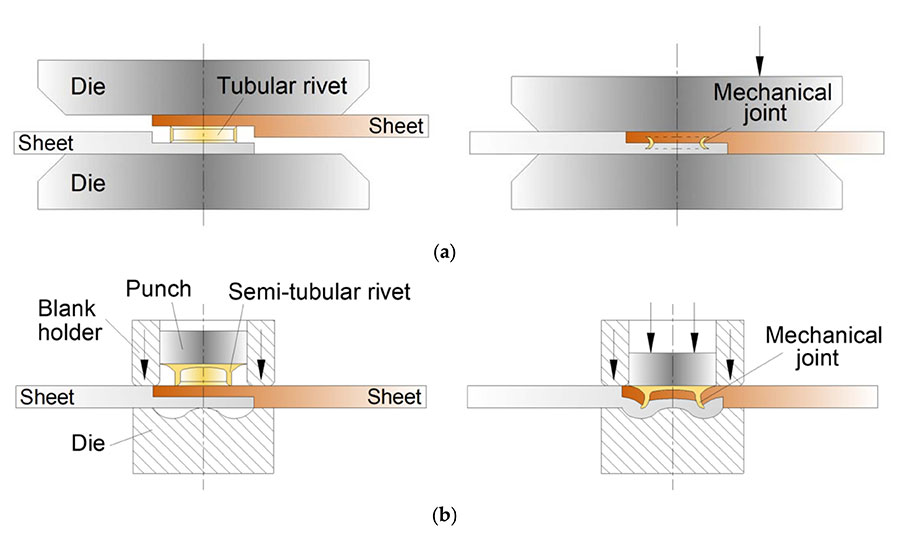
In DSSPR (top), a double-sided tubular rivet creates a mechanical joint between two sheets. The rivet has a simple geometry and remains hidden between the sheets. There is no exposed head on either side. A tubular rivet with chamfered ends penetrates the sheets as they are compressed against each other.
In conventional self-pierce riveting (bottom), a semitubular rivet is driven through the top sheet into the bottom sheet. The rivet is upset, under the influence of a die, into the bottom sheet but does not break through it. The rivet head is flush with the top sheet, but a raised “button” is created on the blind side. Source: Technical University of Lisbon
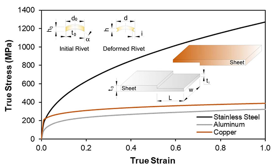
This graph shows the material flow curves for the copper, aluminum and stainless steel used in our study. Source: Technical University of Lisbon
Materials and Methods
To validate our DSSPR method, we conducted strength and electrical tests on several sample assemblies.
Stainless steel tubular rivets were used to produce half-lap joints between aluminum and copper sheets. The sheets were 50 millimeters wide and 5 millimeters thick. The sheets were machined halfway to a thickness 2.5 millimeters and an overlap length 25 millimeters. The rivets were 10 millimeters in diameter and 5 millimeters tall, with a wall thickness of 1.5 millimeters and a chamfer angle of 45 degrees.
The joining process was performed as a one- or two-stroke process at room temperature, either by placing the rivet between the sheets and compressing them into each other or by pre-riveting the harder copper sheet and then pressing on the aluminum sheet.
Strength tests on the assemblies were done at room temperature. The riveted joints were subjected to destructive shear tests according to ISO 12996:2013 to evaluate the maximum force that the joint can withstand before separation starts to occur.
In addition, some joints were cut lengthwise to measure the parameters of the deformed rivet, such as the final height and diameter and the mechanical interlock.
To assess conductivity, the riveted assembly was heated to 105 C. A micro-ohmmeter was then used to measure electrical resistance in the assembly as it gradually cooled to 20 C.
Experimental Results
We found significant differences between the assemblies riveted in a single-stroke process and those that were riveted in a two-stroke process.
With the single-stroke process, we found that the rivet did not penetrate the copper sheet as much as the aluminum sheet, since the copper was harder than the aluminum. In fact, during the joining process, the rivet was unable to penetrate the copper sheet at the same rate as the aluminum sheet. As a result, the amount of penetration in the aluminum increased until strain hardening in the sheet forced the rivet to flare. This resulted in a weaker joint, not only in terms of its mechanical strength, but also in terms of electrical resistance. That’s because proper contact between the sheets and rivet was not guaranteed.
In the two-stroke process, a dedicated compression tool consisting of a bolster and a conical punch was employed to force the rivet through the copper sheet. This ensured that the rivet adequately penetrated the copper. It also created a strain-hardened region in the copper to facilitate subsequent deformation of the rivet.
For the first stroke, the pre-riveting operation, a maximum force of 85 kilonewtons is needed to insert the rivet. For the second stroke, a maximum force of 135 kilonewtons is needed. The joining process is only revealed by a very small protrusion on the surface of each sheet, which resulted from the material flow of the rivet inside the sheets during riveting.
A cross-section of the joint shows that the amount of rivet penetration in the copper sheet increased. In fact, rivet penetration in the copper sheet increased by 0.2 millimeter to a final depth of 1.06 millimeters, whereas rivet penetration in the aluminum sheet decreased by 0.06 millimeter to a final depth of 1.47 millimeters.
More importantly, rivet penetration was complemented by a significant increase in rivet interlocking in the copper sheet, which increased by 0.32 millimeter. With the single-stroke process, interlocking was almost inexistent. An increase in interlocking in the aluminum sheet of 0.02 millimeter was also observed.
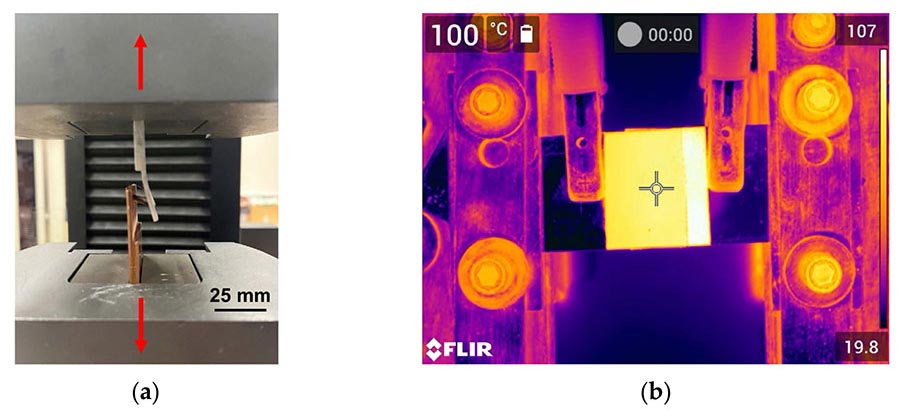
These photos show the setups for the tensile shear tests (a) and conductivity tests (b). For the latter, the riveted assembly was heated to 105 C. A micro-ohmmeter was then used to measure electrical resistance in the assembly as it gradually cooled to 20 C. Source: Technical University of Lisbon
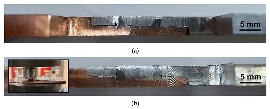
These photos show cross sections of the riveted joints obtained with a single-stroke process (a) and a two-stroke process (b). The inset image shows the pre-riveting tool. With the single-stroke process, the rivet does not penetrate the copper sheet as much as the aluminum sheet, since the copper is harder than the aluminum. Source: Technical University of Lisbon
Mechanical Performance
During tensile shear tests, detachment of the rivet starts to occur in the sheet with lower mechanical strength—in this case, the aluminum one. Instead of shearing, the prevailing failure mechanism was the bending and detachment of the tubular rivet. On average, joint separation began to occur at a force of 5.2 kilonewtons.
As the assembly is forced to separate, the aluminum sheet is heavily deformed in the riveted region, as a consequence of the bending moment generated during the test. In contrast, the copper sheet is not deformed, nor is the rivet, which stays attached to the copper.
For comparison purposes, a riveted joint made from two aluminum sheets with a thickness of 1.5 millimeters withstands a maximum force of 2.2 kilonewtons. A joint made from two aluminum sheets with a thickness of 5 millimeters withstands a maximum force of 10.2 kilonewtons.
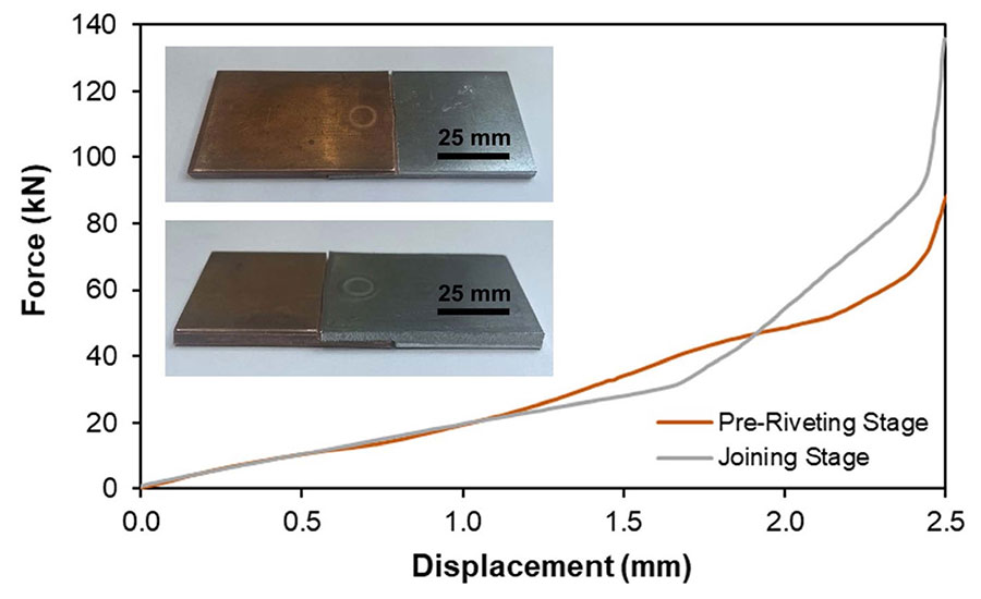
The researchers found that at two-stroke process works best for DSSPR. For the first stroke, the pre-riveting operation, a maximum force of 85 kilonewtons is needed to insert the rivet. For the second stroke, a maximum force of 135 kilonewtons is needed. The differences in both joining stages are more noticeable in the larger displacement values, where the strain hardening effect becomes more pronounced. In turn, an increase in overall force is observed as the rivet ends flare, until the sheets are fully in contact and the joining process is completed. Source: Technical University of Lisbon
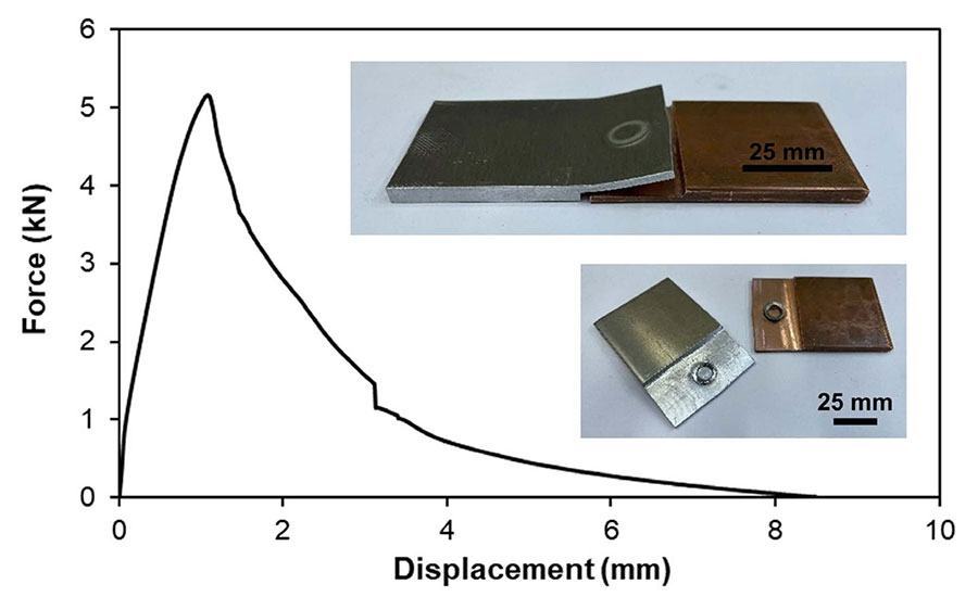
During tensile shear tests, detachment of the rivet starts to occur in the sheet of lower mechanical strength—in this case, the aluminum sheet. Instead of shearing, the prevailing failure mechanism was the bending and detachment of the tubular rivet. The average results of these destructive tests are shown in the graph, where it can be observed that after a maximum force of 5.2 kilonewtons, joint separation starts to occur. Source: Technical University of Lisbon
Electrical Performance
To assess the electrical performance of the riveted joint, the electrical resistance of the assemblies was measured at different temperatures. These temperature distributions were obtained with the thermal imaging camera.
Although the electrical resistivity of the stainless steel rivet is considerably higher than that of the aluminum or copper sheets, the level of pressure generated by the joint ensured a nearly constant value of electrical resistance. In fact, our riveted joint was only slightly less conductive than a comparable joint assembled with a nut and bolt.
On the other hand, the riveted joint was more consistent across a range of temperatures than was the bolted joint. In the riveted joint, the difference in resistivity from 20 to 100 C was just 1.1 milliohms. In the bolted joint, the difference was 5 milliohms.
This increase in resistivity for the bolted joint can be attributed to greater expansion and contraction of the bolt and nut compared with the other materials. This results in less contact between the sheets and, therefore, increased resistivity.
In addition, at high levels of current and voltage, the risk of bolt fracture is increased due to thermal fatigue. In the riveted joints, this phenomenon also occurs, but is limited by the aluminum and copper sheets, whose low electrical resistivity counteracts these movements. Also, the smaller size of the rivet avoids large expansion and contraction cycles, so the riveted joint stays tighter over time. As a result, the electrical resistance of the riveted joint remains almost unchanged for different temperatures and lowers the probability of critical defects occurring during the service life of the joints.
It’s worth mentioning, however, that the machining operation used to create the stepped areas on our copper and aluminum test parts contributed to their better conductivity. The bolted joints, in contrast, were assembled from overlapping sheets that retained their virgin surfaces.
The effectiveness of the riveted joint is also demonstrated by the fact that although the overlapped contact length is half that in the fastened joint, the differences in electrical resistance are not significant. This indicates an increased contact area produced by the riveted joint, which compensates for the reduction in the contact length.
At the same time, the tightening torque of the bolt in the fastened joint has a substantial effect on the contact pressure and, consequently, on the electrical resistance, which can be compromised by self-loosening of the fasteners.
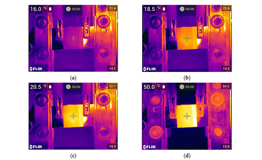
To assess the electrical performance of the riveted joint, the electrical resistance of the assemblies was measured at different temperatures. These temperature distributions were obtained with a thermal imaging camera. Looking at the evolution from image 7a (at room temperature) to image 7b (at 18.5 C), it can be observed that the passage of current is developed in the annular region of the deformed rivet, where the applied pressure is at its maximum, due to mechanical interlocking. In image 7c, after an increase of 2 C, the passage of electric current in that location becomes more noticeable. In image 7d, the temperature distribution becomes homogeneous. Source: Technical University of Lisbon
Looking for a reprint of this article?
From high-res PDFs to custom plaques, order your copy today!


