Pickup trucks are synonymous with durability and ruggedness. But, sometimes just being tough isn't good enough. End users often demand extra power and torque for hauling or pulling heavy loads.
That's why the leading pickup truck manufacturer, Ford Motor Co. (Dearborn, MI), offers a line of heavy-duty vehicles equipped with diesel engines. Two out of every three Super Duty trucks sold are equipped with Power Stroke diesel engines. In fact, Ford sells more than 200,000 per year. International Truck and Engine Corp. (Warrenville, IL) supplies the diesels and has built more than 2.5 million engines at its Indianapolis assembly plant over the past 11 years.
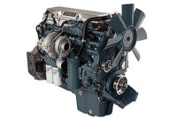
The quiet 6.0-liter Power Stroke engine delivers 570 ft-lb of torque and 325 hp. It uses a high-pressure fuel rail, which delivers fuel to the individual direct-injectors at pressures of up to 26,000 psi. This allows precise metering and complete atomization of the fuel mixture for clean burning. With four valves per cylinder, the engine is able to move large volumes of air and fuel at peak load.
Each engine is equipped with 16-valve bridges, which sit on top of the valve stem. During head assembly, the valve bridges are placed on top of the valve spring and a rocker arm is placed on top of the bridges. This whole assembly is then placed onto the engine.
Prior to being installed on the engine, the valve bridges are only loosely held in place by a rocker arm. It is necessary to inspect each one to ensure they are positioned accurately and that none of the components have become misaligned.
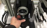
In the past, the inspections were performed manually. An operator would look down into the engine assembly, check each individual valve bridge for placement, and mark each one with a paint pen to indicate that it had been inspected. The process was slow and costly from a labor standpoint.
International Truck and Engine decided to implement a robot-guided inspection system to verify the correct placement of valve bridges during assembly.
"We felt that a robot-guided vision system would be the most flexible solution in terms of being able to automatically inspect the parts inside the engine," says Scott Hauger, an applications engineer who worked on the project. "We could have set up a little finger probe that actually touched the part to do the verification, but the parts are difficult to approach consistently. With vision, we'd be able to avoid any problems associated with a contact approach."
One of initial ideas for a vision system was to have 16 separate vision cameras mounted above the inspection point, allowing for one camera per part. However, the engine assembly is covered with components. Wires and other parts often obstruct the valve bridges. According to Hauger, a 16-camera vision system would have been an expensive option that would require extra maintenance.
"We needed a way to allow a single-vision camera to move in and around the engine to actually get a look at the parts even when other things are obscuring them," says Hauger. "Positioning the camera with a robot allowed us to implement logic that enabled the robot arm to see the valve bridge from multiple angles."
The main components selected for the project included a single In-Sight 3000 vision sensor from Cognex Corp. (Natick, MA) and a six-axis IRB 140 robot from ABB Inc. (Auburn Hills, MI). The In-Sight 3000 is a high-performance sensor that consists of an industrial-hardened, DSP-based vision processing unit; a high-speed digital camera that easily mounts to the robot arm; an onboard light control; built-in discrete I/O; and a preinstalled vision library of grey-scale vision software tools. It also provides a standard VGA output for real-time display, built-in Ethernet communications, and an onboard serial port that is linked to the ABB robot controller.
To set up the 16-point inspection routine, Hauger and his colleagues used the vision sensor's spreadsheet interface. It enabled them to quickly select vision tools and parameters from drop-down menus, and configure a customized operator interface to make day-to-day operation of the system easy for line operators, technicians and maintenance staff.
"It was easy to explain how it works to shop floor personnel," says Hauger. "People with no programming experience were able to make changes to the program in one day."
Engine blocks enter the cell on a floor-mounted conveyor. Each engine sits in its own nested pallet. Once an engine is present, the robot hovers over the pallet and adjusts its position until the vision camera can get a good view of the parts. If the camera can't see a part, the robot repositions itself at various angles until the part becomes visible. To increase visibility, the parts are illuminated with a combination of a ring light, which is attached to the tooling on the end of the robot arm, and side-mounted fluorescent lighting.
Once a valve bridge is in view, the robot controller sends a signal to the vision camera to capture an image of the part. The image is then sent to the vision processing unit, which is mounted in the robot controller enclosure. It is processed with In-Sight's PatFind tool, a geometric pattern-matching software tool that verifies the correct position of the part despite any occlusions or variations in part appearance that may exist.
Pattern-matching performance factored heavily into the decision to go with the machine vision system. "The valve bridges have a unique shape," explains Hauger. "With so many components in the way, it's critical that the vision system is able to pick out the right features."
The PatFind tool analyzes images using geometric information in place of pixel grid-based correlation. For example, it interprets a square as four line segments and a football as two arcs. By analyzing the geometric information from a part's features and spatial relationships, the tool is able to repeatably determine the precise position of each valve bridge in the engine regardless of how it appears.
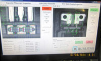
As each of the 16 valve bridges is inspected, operators can view a live image display of the parts on a nearby color monitor. The display lists the different valve bridges by cylinder number, and provides pass-fail information for each inspection.
If all 16 parts pass inspection, the engine proceeds down the production line to a testing area. If a failure is reported, the robot controller passes the information to a line control system to be written to an RFID tag. At that point, the engine goes into a repair loop where an operator manually inspects the parts in question. It is then rerouted through the cell and inspected by the vision system again.
Since the robot-guided inspection system was installed two years ago, it has been running nonstop for two shifts per day without any problems. Hauger claims that product quality has remained consistently high.


