Manufacturers are increasingly imprinting permanent, 2D, machine-readable Data Matrix codes directly onto individual components as they enter the value stream.

For today’s engineers, information is critical-real-time, accurate data that allows them to do everything from fine-tune their assembly lines in response to changing production targets to identify quality problems and weed out defective parts.
With this in mind, manufacturers are increasingly imprinting permanent, 2D, machine-readable Data Matrix codes directly onto individual components as they enter the value stream. The result can be anything from a basic “license plate,” simply identifying the part, to what Carl Gerst, senior director and business unit manager for ID products at Cognex Corp. (Natick, MA), calls a “portable database,” with a wealth of historical data on each component. The latter can be especially important in the event of product recalls or a warranty situation, since it can help engineers track a problem directly to its source.
Of course, as is the case with so much in manufacturing, the concept is one thing, execution another. No matter what the industry or the kind of data being encoded, engineers need to ensure that each component is marked so that the data will be easily read: either hours later during processing, or years after the part has gone into service. This means accounting for a number of different factors, including the hardness and texture of the base material, the location of the Data Matrix code on the part, and the component’s basic geometry.

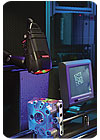
An increasing number of industries is using direct part marking to enhance process control and help resolve warranty issues. Photo courtesy Microscan Corp.
Code Requirements
Although they look much like tiny crossword puzzles, each Data Matrix symbol is, in fact, comprised of a number of distinct regions, or zones. For example, running along two sides of each Data Matrix symbol you will find either two solid lines or a series of dots forming what looks like an “L.” This is called the finder pattern and allows a reading system to precisely locate the code within its field of view.Running along the other two sides of the square will be lines of alternating squares or dots-depending on the method used to place the symbol. These represent the clocking pattern for the code, and serve to define the contrast between the light and dark portions of the symbol.
Contained within these two regions is the actual data region, made of up of lines of light and dark dots or squares-called elements, modules or cells-each representing one bit of binary data. Depending on its size, a Data Matrix symbol can store anywhere from six to more than 3,000 digits in a single code. Data Matrix symbols can be made as small as 2 millimeters across, but typically measure 10 millimeters or more to enhance data capacity and readability.
No matter what the dimensions, it is essential that the code have perfect right angles, that the contrast between the elements be consistent and that the elements are uniformly sized. Often, a symbol can be read even if it is scratched during assembly or while in use. But, if the symbol is afflicted by something more basic, like uneven cell size or poor mark quality, then it may be rejected.
In addition, every Data Matrix symbol must be surrounded by a “quiet zone” if it is to be easily readable by a machine vision system. According to Bob Taplett, applications engineering manager at Microscan Systems Inc. (Renton, WA), this area should be at least as wide as a single symbol element and free of any text, marks other objects to ensure the highest level of readability. Unfortunately, in practice, this can be difficult to achieve, making quiet zone violations a common source of problems in the field.
When choosing marking technologies, engineers have a number of options, depending on the type of component being marked. For example, when marking glass or creating clean, high-resolution marks on metal or plastic, many engineers select the laser-etch approach. This marking method is more expensive, but is extremely reliable and requires neither consumables nor the periodic replacement of worn parts. Laser markers create clean, square-shaped, low-contrast cells on metal, and medium-contrast cells on glass.
At the other end of the cost spectrum are ink-jet printers. Unlike laser markers, ink jets create round dot-like cells, and require the use of a consumable. Inked symbols are also not considered to be “permanent” in many industries: for example, in the automotive industry where a mark will be expected to endure years of often dirty or greasy conditions. Still, Cognex’s Gerst says this is not necessarily a hard and fast rule, noting that ink jet is used in some applications, such as marking plastic pharmaceutical bottles, where product life expectancy is relatively short.
Between these two extremes are dot-peen markers, in which a pneumatic or electromagnetic driver is used to create the code pattern with the help of a hardened-carbide or diamond-tipped stylus. This approach can be used on a variety of surfaces, including steel, plastics and glass, and requires no consumables, although the styli need to be periodically replaced. Like laser markers, dot-peen markers create permanent marks-either round or square depending on the stylus-and are well suited to use in an automated environment. On the downside, dot-peen marks are often low contrast. This can result in reading problems down the line, unless good contrast can be created in the images with correct illumination.
Finally, there is electro-chemical etching, which requires the use of a low-voltage current and stencil. In contrast to the other three technologies, this technique, does not lend itself to high-volume production. However, it creates precise marks and does not weaken or distort the metal substrate, making it a good choice when marking fragile and thin-walled parts. For this reason, it is sometimes used in the semiconductor industry.
Note that the base material is not the only factor when selecting a marking machine. According to Pannier Corp. (Pittsburgh) supervising sales engineer, Kurt Olyarnik, the amount of space available can be just as important, if not more so.
“The resolution and permanence of the laser-marked Data Matrix makes it the best application method where real estate is limited. A Data Matrix mark applied using the continuous ink-jet technology approaches the resolution of a laser, but lacks the permanence. Percussion marking requires the most real estate, but is the least expensive application method. We refer to a percussion marker as a ‘cheap laser,’” Olyarnik says.
Along these same lines, Toch Uk, application engineering manager at Technifor Inc. (Charlotte, NC), says throughput can be a factor, because increased speeds will inevitably lower symbol quality. This, in turn, can impact the choice of technologies.

Although it’s possible to imprint Data Matrix symbols on curved surfaces, engineers need to make
sure doing so will not affect readability. Photo courtesy Cognex Corp.
Location, Location, Location...
When selecting where best to place a Data Matrix code, engineers should remember that it’s all about the data-ensuring that it is readily accessible and easy to read when needed. For example, Gerst says the location should be clearly visible throughout the manufacturing process, not just when it is being applied. “The location of the code on the part can directly impact…readability,” Gerst emphasizes. “Choose a…prominent position on the part that is easily viewed by the reader.”Similarly, engineers need to be sure the surface of the part is conducive to easy reading and that the symbol location is not affected by shadows or other types of interference.
For example, Joshua Jelonek, project manager for vision and marking technology at Keyence Corp. of America (Woodcliff Lake, NJ), says he had a customer that was marking small Data Matrix codes on a plastic surface that was generally flat and smooth, but had a raised plateau near the edge of the part. “When a portion of the code was placed on the raised surface, the readability dropped considerably,” Jelonek says. “Larger codes tend to be more robust, but code placement becomes critical when applying smaller codes.”
Finally, there is the surface itself. On the one hand, Pannier’s Olyarnik says you want it to be as flat as possible. On the other, you want it to be smooth enough that its basic texture won’t interfere with the symbol.
For example, when working with cast parts, Thomas Phipps, CEO of Columbia Marking Tools Inc. (Chesterfield, MI), says it often makes sense to go with a more expensive laser marker, because this technology is better at marking rougher surfaces. Another option is Columbia’s “diamond scribe” system, which accomplishes much the same thing. With standard dot-peen markers, there is the danger that surface imperfections will be confused with the code’s dots when a reader scans the symbol.
In terms of curvature, Gerst says engineers are not limited to areas that are perfectly flat, but they need to be extremely careful. “Cylindrical parts are challenging, because surface curvature can create distortions to the code and make proper illumination of the code very difficult. To mitigate this problem, a code size that is no larger than 16 percent of the diameter or 5 percent of the circumference of the part is required,” Gerst says.
Microscan’s Taplett adds that engineers should minimize the width of the code following the curve. “An example of a poor choice of placement would be a round metal part laser etched with a square Data Matrix with a width greater than 16 percent of the curve around the part. A better choice would be a rectangular code of two stacked Data Matrix symbols,” Taplett says.
Again, it’s all about the data. Just because a laser etcher or dot-peen marker can create what appears to be a good symbol, that doesn’t mean it will work as intended. “Typically, marking systems can mark [a round part] either within the plane of the stroke of the pin or with use of a rotary axis,” Phipps says. “The difficulty is in lighting and reading, as the light is bright on one side of the diameter and dark on the other. It can be done, but why make it difficult when it doesn’t have to be?”
In terms of specific applications, Technifor’s Uk says needs vary depending on the industry. For example, in the medical sector, code sizes tend to be small, but surfaces clean, whereas in the automotive industry conditions vary widely depending on the situation. In the aerospace industry, engineers need to be careful that their Data Matrix symbols don’t compromise the mechanical properties of critical parts. Engineers also need to be aware of the many regulations governing part marking in aerospace manufacturing.
With this in mind, engineers should always think about their marking needs before signing off on a component’s design, so they aren’t stuck trying to find a spot that will accommodate a code later on.
“It should be treated like any other part of the manufacturing process. In [direct part marking] phrases like, ‘no place to mark, no room for marking equipment, no budget, no time to properly design-in the best method,’ are commonplace,” Phipps says. “Marking is usually the last thing on the manufacturer’s mind.”
Taplett agrees. “The earlier the better…. Designing marking and reading locations into the assembly line can save money, increase throughput and improve overall process control,” he says. According to Taplett, this kind of forethought is especially prevalent in the electronics industry, where circuit boards are often designed with space left blank to accommodate different types of codes.
Whatever the point in the design process, today’s Data Matrix marking and reading systems are relatively easy to integrate into an automated production environment. “With the technology of today, the integration of the marking system is straight forward. Most marking systems can communicate with PLCs via RS232 or RS422 serial communications or via Ethernet TCP/IP,” Pannier’s Olyarnik says. “The manufacturers of marking equipment have built in the necessary commands and have made them accessible via simple-to-use protocols.”
Phipps add that automated systems are often well suited to the integration of a part marking system by their very nature. “The parts are usually in a production mode and are already being held for other precise assembly or manufacturing reasons,” Phipps explains.
No matter how the Data Matrix symbol is created, Gerst says it is increasingly common to install a verification system to ensure that the part marks meet the quality levels set forth by industry standards.
“Until recently, manufacturers implementing [direct part marking] have lived with varying levels of read rates, in some cases approaching the upper 90 percent level. However, this level of performance is no longer acceptable,” Gerst says. “Solution providers must demonstrate that they can achieve Six Sigma read rates, a level of quality that equates with only 3.4 defects per million opportunities. To achieve this read rate it is important to plan, understand and implement a marking solution that builds in quality to ensure these results.”


