Flow-Drilling Screws Help Carmakers Shed Weight
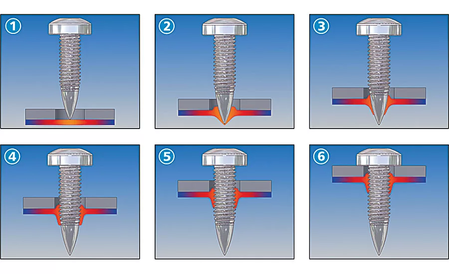
The installation process for friction-drilling screws has six distinct steps: heating (1), penetration (2), extrusion forming (3), thread forming (4), screwdriving (5) and tightening (6). Illustration courtesy EJOT GmbH & Co. KG
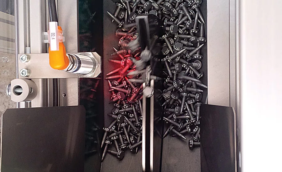
Friction-drilling screws require gentler handling than ordinary screws. DEPRAG’s sword feeder solves that problem. Photo courtesy DEPRAG Inc.
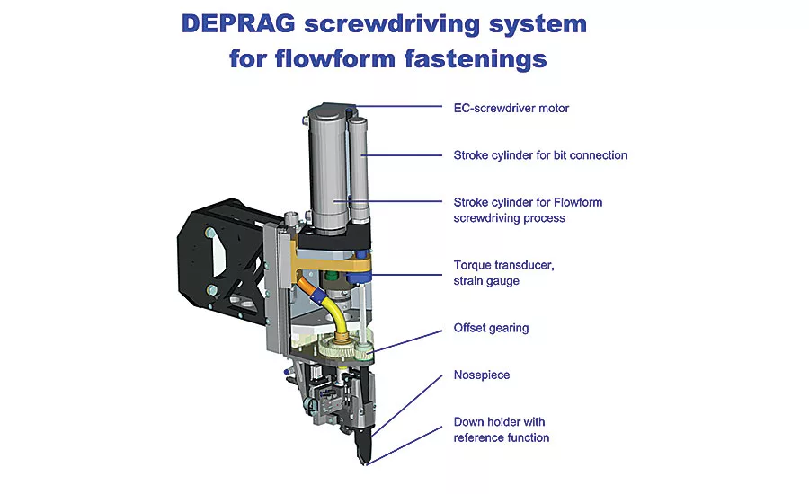
Because there are additional variables beyond torque and angle to measure and control—driver speed, axial force and fastener depth—friction-drilling screws require sophisticated driving technology. Photo courtesy DEPRAG Inc.
Engineers must allow clearance for the driver and tooling, as well as for the cylinders that apply axial force during fastening. Photo courtesy DEPRAG Inc.
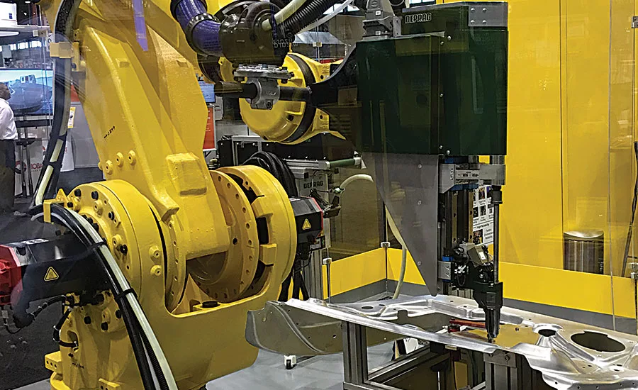
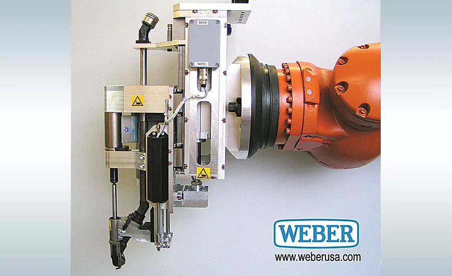
If a six-axis robot will be used to install friction-drilling fasteners, engineers should choose a model that can hold up to the forces involved. Photo courtesy Weber Screwdriving Systems Inc.
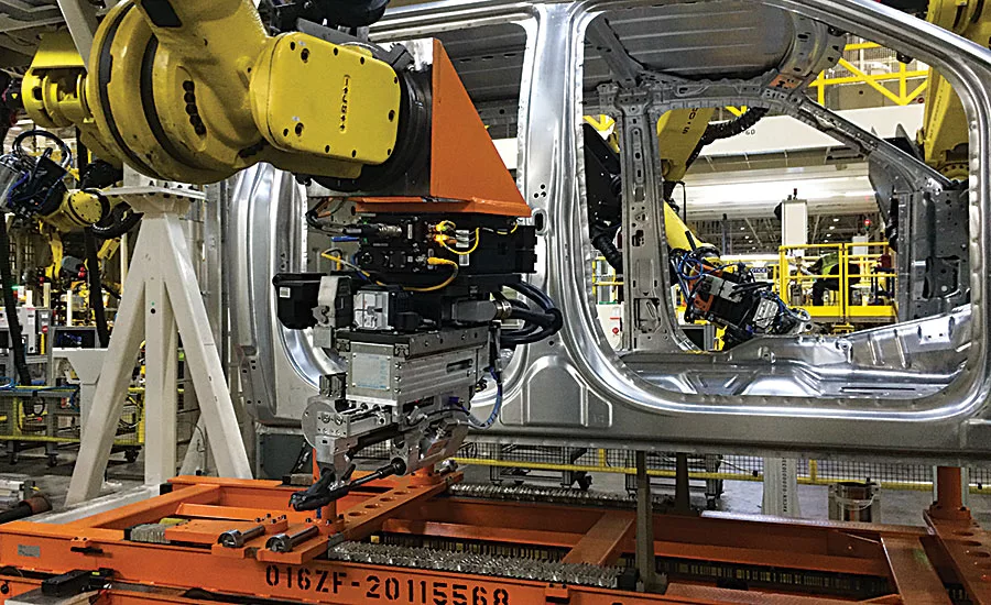
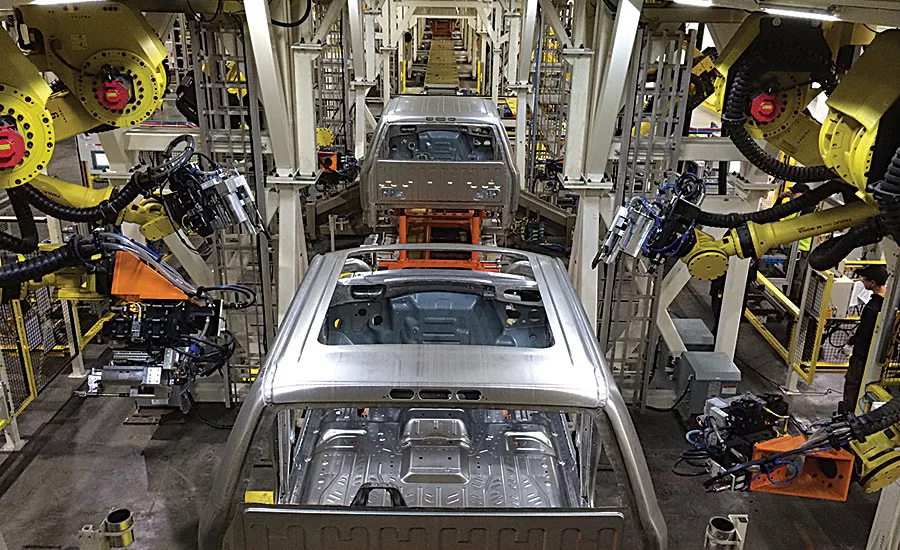
Friction-drilling screws play a key role in the assembly of the Ford F-150. Photo courtesy Weber Screwdriving Systems Inc.
These automatic screwdriving systems monitor torque, speed, thrust and fastener depth through the fastening process. Photo courtesy Weber Screwdriving Systems Inc.
At first glance, the Ford F-150 and the Chevrolet Corvette would appear to have nothing in common, beyond the fact that they’re both gas-powered vehicles. After all, you wouldn’t tow a bass boat with a Corvette any more than you would zip a 5,000-pound pickup around a test track.
However, the same small component plays a key role in the design and manufacture of both vehicles: the friction-drilling screw.
That’s because the bodies of both vehicles are largely made from aluminum, which helped reduce their weight significantly. For example, the aluminum frame of the 2014 Corvette is 99 pounds lighter and 57 percent stiffer than the previous-generation steel frame. The 2015 F-150 is 700 pounds lighter than its predecessor.
Faced with the need to join aluminum to aluminum and aluminum to steel, GM and Ford have been forced to find alternatives to the tried-and-true spot welding technology they had been using for decades to join all-steel assemblies. Friction-drilling screws are one such alternative.
Although friction-drilling screws have been around since the late 1990s, the fasteners are increasing in popularity due to the continued emphasis on “lightweighting” in the auto industry; a greater familiarity with the technology; and advances in the equipment for installing them.
“The early adopters in this country are now on their second or third programs [with friction-drilling screws],” says Jim Graham, president of Weber Screwdriving Systems Inc. “In Europe, the technology has been on solid footing with automotive OEMs since 2002.”
Besides the Corvette and the F-150, friction-drilling screws are being used in many other vehicles, including the Cadillac CT6; Acura NSX; Mercedes-Benz SLS; Audi TT, A4, A6 and A8; Porsche 911 and Boxter; Lotus Evora; Jaguar XK; Ferrari California; and Lamborghini Gallardo. Auto parts suppliers are also taking advantage of the technology. For example, Hella is using friction-drilling screws to assemble its Bi Xenon headlamp modules.
Looking for quick answers on assembly and manufacturing topics? Try Ask ASM, our new smart AI search tool. Ask ASM
The fasteners are also seeing interest from manufacturers of white goods, aircraft, fabricated metal products, and buses and heavy trucks.
Going With the Flow
A friction-drilling, or flow-drilling, screw is a self-piercing and extruding fastener for joining layers of sheet metal. Combining the properties of friction drilling and thread forming, the screw acts as both a fastener and a drilling-and-tapping tool. It penetrates the layers, extrudes a short boss, forms its own threads, and applies clamping force between the sheets.
The fastener has a wide, flat head; a relatively thick shank; and a pointed tip. The head can be designed for external or internal drive systems (including hex head, TORX, TORX plus and cross recesses), and the bottom surface of the head can be undercut. The shank is divided into three zones: a pointed, unthreaded tip (for drilling); a short partially threaded midsection (for thread-forming); and a fully threaded upper section (for applying clamp load).
The installation process has six distinct steps: heating, penetration, extrusion forming, thread forming, screwdriving and tightening.
“It takes 2 to 3 seconds to drive one of these fasteners,” says Boris Baeumler, applications engineer at DEPRAG Inc. “In that time, we change the driving parameters four times.”
In the heating step, the tip of the fastener is pushed against the material with high force and rotated at high speed. Friction between the screw and the material heats the surface to 150 to 250 C, depending on the materials and how thick they are.
“At the beginning of the cycle, you want a lot of down-force to help generate friction,” says Baeumler. “With aluminum, you need less force, say, 1,500 to 2,000 newtons. With steel, it might be 1,800 to 2,500 newtons.
“Driver speed is also important. Aluminum tends to dissipate heat quickly, so we run at a higher speed, say, 6,000 rpm. With steel, we tend to run at slightly lower speed, perhaps 4,000 rpm.”
As the materials heat up and get soft, the fastener starts to penetrate the stack and create a hole. The material extrudes up and down along the points of the screw, forming a boss.
“As soon as the fastener penetrates the material, we reduce the down-force,” says Baeumler.
The fastener continues to penetrate the material stack until the tip penetrates the bottom of the stack. The conical geometry of the fastener helps to extrude a short boss on the bottom side of the stack.
Next, female threads are created in the extrusion by the thread-forming zone of the fastener. This step is performed at a lower speed—approximately 2,000 rpm. After the threads are created, the screw is threaded into the newly created nut member until its head seats against the top sheet. This is performed at 200 rpm, to avoid damaging the newly created threads.
Finally, the fastener is tightened to a preset value.
“We monitor all the variables—torque, speed, thrust and fastener depth—all the way through the process, and we feed that data back to the motion controller,” says Graham.
Assembly Advantages
Compared with spot welding, clinching, self-piercing rivets and conventional threaded fasteners, friction-drilling screws have many advantages. For starters, they are installed from one side of the assembly. Access to the opposite side of the assembly is not necessary. That’s a real advantage, since the C-frame tooling for clinching or riveting can be difficult to maneuver with a robot.
In addition, friction-drilling screws create strong joints. Tests on high-strength sheet steel indicate that friction-drilling screws produce joints with greater peel strength than spot welding, clinching, self-piercing rivets. Tests of sheer strength show that friction-drilling screws performed at least as well as clinching and self-piercing rivets and only slightly less than spot welding.
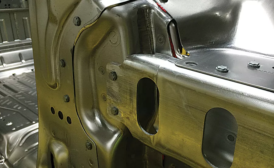
Because the fastener drills its own hole, there’s usually no need to punch or drill holes in the materials or to align the holes prior to assembly. There is a caveat, though. As the fastener is forming a boss, most of the material flows out, toward the bottom of the stack, but a slight amount also flows up, toward the driver. A recess under the head of the fastener is often enough to capture this material. However, if the layers are particularly thick, if three or more layers are being fastened, or if one of the materials is incompatible with the process, a “clearance hole” may be needed in the top layer. This will prevent the formed boss from creating gaps between layers.
“You need to provide a place for the material to flow,” says Baeumler.
Another advantage of friction-drilling screws is their higher drive-to-strip ratio compared with thread-cutting screws, especially with thinner sheet metal. “With thin sheet metal, especially steel, it’s common to strip out self-drilling screws,” Baeumler points out. “The difference in torque between driving a screw and stripping it is extremely small. Friction-drilling screws form out the material, so there’s more material for the screw to engage, and the torque window is a lot bigger.”
And, like conventional threaded fasteners, friction-drilling screws can be removed and replaced for serviceability. There are no issues regarding thread tolerances, because the fastener creates and engages its own threads at standard pitches. But, unlike thread-cutting screws or drilling-and-tapping operations, friction-drilling screws do not create waste. No chips are generated during installation.
Installation Technology
Friction-drilling screws cannot be installed with just any screwdriver. Because there are additional variables beyond torque and angle to measure and control—driver speed, axial force and fastener depth—friction-drilling screws require sophisticated driving technology and are typically installed with fully automatic equipment. The driver can be mounted to a linear actuator or, more typically, a six-axis robot.
Installing friction-drilling screws “is not like traditional screwdriving applications, where the fastener is a commodity item,” says Baeumler. “When you specify these fasteners for a project, you need to consider the equipment at the same time, even at the design stage.”
Parameter settings, such as driver speed and axial force, vary depending on the thickness of each sheet, the number of layers, the properties of each material, surface treatments and overall joint requirements. Thorough testing on coupon assemblies is imperative.
Another difference between standard automatic screwdrivers and equipment for friction-drilling screws lies with how the fasteners are fed. Despite their relative bulk, friction-drilling screws require gentler handling than ordinary screws. That’s because the tip, which initiates the friction, is critical for the application. Dumping the screws into a vibratory feeder is not an option.
To solve that problem, Weber uses a step-feeder to deliver the fasteners, while DEPRAG uses its patented sword feeder. DEPRAG takes the additional precaution of blowing the fasteners head-first through the feed tube, instead of point first. A revolving mechanism in the drive head flips the fastener for installation. As a side benefit, the extra revolving step ensures that there’s always a screw ready in the drive head for the next cycle.
A high-volume automotive body line can consume a lot of fasteners, so reliable feeding is critical. Screwdriver suppliers have solved that challenge a couple of ways.
Weber developed a dual-tube feeding system. Two feeding tubes run to the drive head. If one tube gets jammed, the driver automatically swaps to the backup tube.
DEPRAG has developed a different method. Rather than blow the fasteners to the driver—and add one more tube to the robot’s dress-out package—DEPRAG can supply the drive head with a swappable, reloadable magazine. Each magazine holds 30 screws. While the robot is installing fasteners from one magazine, a standalone feeding station is reloading another.
Yet one more difference between standard automatic screwdrivers and equipment for friction-drilling screws is in the jaws on the drive head. Screwdrivers for friction-drilling screws have “active jaws” rather than spring-loaded jaws, explains Graham. The powered jaws hold onto the screw until the tip has correctly engaged the material. In the past, the screw might have fallen over.
Early this year, both Weber and DEPRAG will release new versions of their friction-drilling screwdriving equipment.
Graham says the third generation of Weber’s equipment for installing friction-drilling screws is “a quantum leap” from previous iterations, offering faster driver speeds (as much as 11,000 rpm), higher axial thrust, and greater control over the installation process.
“Now, we can accommodate different screw geometries,” says Graham. “We can fasten steel alloy sandwiches, steel-carbon sandwiches, or any combination of materials.”
If a six-axis robot will be used to install the fasteners, engineers are well-advised to choose a model that can hold up to the forces involved.
“Once the screw is in position, the robot must provide a very solid backstop so the driver can generate the necessary downward thrust,” says Graham. “The last thing you need is to start pushing on the assembly and have the robot move away.”
To that end, robot suppliers are stepping up to the plate. For example, FANUC America Corp. recently introduced its new M-900iB/280 robot at the Fabtech show last November in Chicago. The robot was shown simulating the installation of friction-drilling screws on an automotive door panel assembly.
The robot’s casting shape has been optimized to provide enhanced arm rigidity compared to previous models. The robot has a 2.65-meter reach and a compact wrist with heavy payload capacity. FANUC engineers enhanced the allowable load inertia at the wrist so the robot could handle heavy objects with stability.
Design Issues
As with any automatic screwdriving application, engineers need to provide room for the tooling to access the fastening location. A flat, open area with at least 10 to 12 millimeters of clearance is good. Room should also be provided on the back side of the assembly to accommodate the formed boss and the projecting screw point. Friction-drilling screws cannot be installed in a solid block of metal.
If a six-axis robot will be used to install the fasteners, engineers need to provide enough room for the robot to access the driving locations. Engineers should allow clearance for the driver and tooling, as well as for the cylinders that apply axial force during fastening.
“You can’t drive these screws in spots where you have close vertical restrictions,” says Baeumler.
The part itself—and any fixturing—should be designed to accommodate the axial force applied during fastening.
“With thinner materials, we can reduce the down-force [to avoid crushing the part],” adds Baeumler. “However, there’s a trade-off. Friction will take longer to heat the part, so cycle time will increase.”
Finally, it’s also worth noting that friction-drilling screws are not the sole answer to joining structural aluminum components. Indeed, multiple technologies are used to assemble the F-150’s body-in-white, including self-piercing rivets, structural adhesives, clinch joints, spot welds, laser welds, friction welds, and good old-fashioned nuts and bolts.
Looking for a reprint of this article?
From high-res PDFs to custom plaques, order your copy today!


