Automated Assembly System Roundup
Auto parts, plumbing products and medical devices are among the myriad items made on automated assembly systems
There’s nothing quite like a multistation automated assembly system. Watching robots, actuators and indexers go about their carefully choreographed routines with little or no human intervention can seem nothing short of miraculous.
The following systems exemplify the hard work and creative engineering that routinely go into today’s automated assembly systems.
System Assembles Medical Device With Multiple Variants
High-speed assembly of medical devices poses multiple challenges. Beyond the sheer volume requirement, medical device assembly systems must also meet cleanliness, process validation and regulatory requirements.
Based in Cookeville, TN, ATC Automation has been designing and building automated assembly systems for 42 years. For the past 12 years, the company has been focusing particularly on medical device manufacturing.
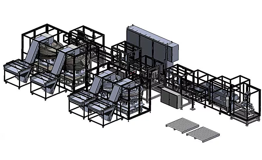
Recently, the systems integrator was approached by a long-time customer to assemble a medical device at a rate of more than 300 parts per minute. The process would essentially involve pressing two plastic parts together. The finished product is about 1 inch in diameter and 3 inches long. Both the upper and the lower housing come in two geometric variants and several different colors. Orientation of the parts is critical to downstream processes.
ATC designed and built a line with four stations positioned around a conveyor loop. To meet cycle time, screw feeders transfer pucks in and out of each station on the conveyor in 400 milliseconds, leaving 800 milliseconds of dwell time to perform work on the parts. Pucks are trafficked by powered gates, and puck traceability data is maintained by bar code readers at every station. Six completed assemblies are off-loaded every 1.2 seconds to a tray management system for further processing.
Station 1 orients and places the lower housing onto the main conveyor. The housings are fed using vibratory bowl feeders. A machine vision system determines the orientation of the part. During transfer to the next position, stepper motors integrated into the transfer nest orient the parts independently to the proper radial position. The housings are then placed into an asynchronous queue.
Looking for quick answers on assembly and manufacturing topics? Try Ask ASM, our new smart AI search tool. Ask ASM
Next, a cam motion is used to complete the placement of the housings into pucks on the main conveyor. Two servos, acting in tandem, lower to drive cam followers along a path to pick up housings from the queue while simultaneously placing them into pucks on the main conveyor. When the cylinders raise, the housings are handed off and their orientation is flipped vertically between two grippers so that, when lowered again, the process can start over.
Once loaded, the pucks are indexed out of the screw feeders, triggering a machine vision system to take and evaluate images of the parts on the fly. These images measure the height of the housing, checking for missing or extra material from the molding process.
Measuring six parts in 400 milliseconds, this system can find height abnormalities of less than 20 microns. For reference, a single grain of table salt is 100 microns in diameter, a human hair is 70, and the smallest thing the human eye can see is about 40 microns.
As the pucks leave the station, a bar code scanner reads 2D Data Matrix codes on top of every puck and associates part-presence and pass-fail data with each puck, again, on the fly.
Next, the pucks travel to station 2, where the tops are assembled. Multiple screw feeders feed and precisely locate pucks along the entire length of this station. A pre-feed screw loads eight pucks in one second, ready for top placement. The other two screws run together, locating and feeding pucks from the top-placement position to the top-press position in one motion. Tops are fed eight-up to this station using two vibratory bowl feeders. Because of a distinguishing feature on the side of the part, the tops enter the escapement in a known orientation. A servo-controlled gripper escapes the parts from vibratory in-line tracks and sets them onto the lower housings.
The pucks are then indexed to the press position, where color vision sensors take an image and determine if the correct color and geometry variant of the top has been placed. Servo presses then push the tops onto the lower housings, and the force and distance profile of each press is monitored to ensure the maximum force, minimum force and pressing distance are within customer specifications. As pucks are indexed, bar codes are scanned, and pass-fail data gathered at the station is associated with each puck.
Screws are again used for positioning at station 3, the reject station. A bar code reader scans the pucks as they enter the station and determines if each puck contains a good part, a bad part, or no part. A high-speed pick-and-place unit picks rejected parts from the pucks and places them into a reject bin. Pucks with good parts are indexed to the off-load station.
At station 4, screws index six pucks at the off-load point, and a bar code scanner scans the pucks to distinguish between empty pucks and pucks with good parts. A high-speed pick-and-place unit deposits good parts to an off-load chute, where they will end up in a tote or quality audit bin for off-line inspection.
For more information, call ATC Automation at 931-528-5417, visit atcautomation.com, or stop by the company’s booth at The ASSEMBLY Show.
System Assembles Covers for Outdoor Faucets
Any homeowner who lives in a cold climate knows the routine of getting the house ready for winter. Rake leaves. Replace screens with storm windows. And, install insulating covers on outdoor faucets to keep them from freezing.
Measuring 6 inches tall and 6 inches wide, a faucet cover is a simple assembly, consisting of a molded Styrofoam cover, an open-cell foam seal, and a loop of cord with a sliding lock. To install, place the loop around the faucet handle, pull the cord away from the house, and slide the lock to hold the cover firmly against the house.
Considering that there are more than 75 million standalone, single-family homes in the United States, the potential production volume for this humble product is immense. Automation is the only way to go.
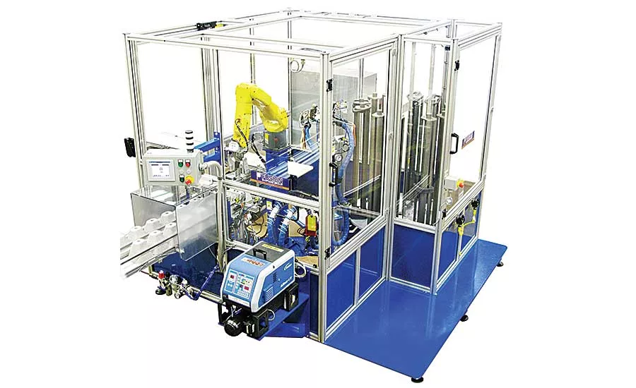
Based in Willoughby, OH, Fusion Systems Group recently designed and built a six-station, rotary indexing dial system to automatically assemble Styrofoam faucet covers. The system produces two cover assemblies with each cycle, for a rate of 1,200 units per hour.
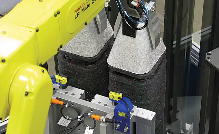
At the start of the process, covers are manually placed onto an in-feed conveyor in stacks of 16. The covers are separated from the stack, one at a time, by a custom-designed stack feeder. The feeder lifts the stack, separating the bottom cover from the stack. Once the stack clears the bottom cover, a stop gate opens to release it from the feeder. The conveyor then transports the cover to a pick-up station.
Next, a six-axis robot picks up two covers and moves them to the glue station. There, an applicator dispenses a bead of hot-melt adhesive around the bottom edge of each cover. The dispense valve is stationary; the robot moves the part.
Next, the robot moves the covers to the seal-assembly station. This station consists of 12 vertical seal magazines mounted to a six-station rotary indexing table. Foam seals are loaded onto a series of mandrels attached to a carousel. The carousel rotates the mandrels to a lift station, where a programmable linear actuator lifts the entire stack of seals far enough to allow the robot to access the top one. Once the entire stack of seals is depleted, the carousel rotates a full magazine into position.
The robot orients the covers over the seals, aligning the bottom edge of each cover to a corresponding seal. Once aligned, the robot presses the covers onto the seals, bonding them together.
Finally, the robot moves the completed assemblies onto a discharge conveyor.
“The most challenging aspect of the assembly system was designing the stack feeder,” recalls Tony Straniero, marketing manager for Fusion Systems Group. “The stacks are over 36 inches tall, and the individual covers have a tendency to stick together. Keeping the stacks from tipping over on the conveyor and separating the individual covers were the most challenging parts of the design process.
“To keep the stacks from tipping over, guide rails were arranged in a multi-tier pattern to support and guide the stacks vertically at several key places. Since the sides of the covers were angled, the guide rails were placed at the narrowest section of a cover, just under the base of the cover above it. This method vertically locked the stacks in position and kept them from tipping.”
To prevent the covers from sticking together, two pneumatic stop gates with tapered fingers extend over the base of the bottom cover in the stack. The lift mechanism then extends under the base of the second cover in the stack and lifts the upper stack of covers. The tapered fingers hold the bottom cover against the conveyor belt, while the stack is lifted high enough to clear the bottom cover.
Once the stack is high enough, the stop gates retract and release the separated cover. The cover is then conveyed to the pick-up station. When the cover clears the magazine, the lift assembly lowers the stack back onto the conveyor, and the process repeats.
With tooling changes, the system can accommodate product variants. For more information, call Fusion Systems Group at 440-946-3300, visit www.fusionsystemsgroup.com, or stop by the company’s booth at The ASSEMBLY Show.
Robotic System Produces Brake Assemblies
The North American automotive industry sold some 17.2 million vehicles in 2018. Assuming each vehicle has four brakes (one for each wheel), that’s 68.8 million assemblies. That’s a lot of brakes.
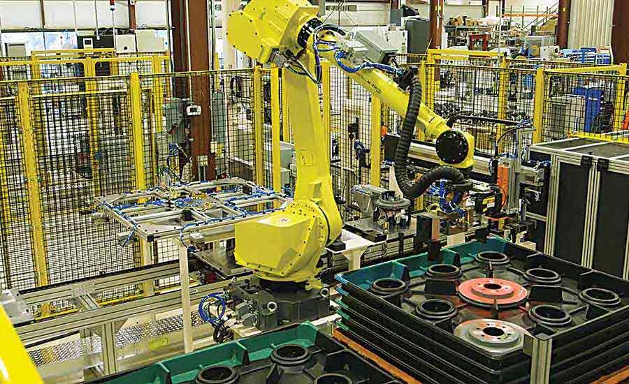
A multistation robotic assembly system designed and built by Edgewater Automation in St. Joseph, MI, is making a dent in that production requirement. The conveyor-based system assembles a brake corner assembly for a major automotive customer at a rate of 120 per hour. Measuring 12 by 12 by 15 inches, the assembly consists of 17 parts.
Vibratory bowl feeders equipped with air jets feed small parts. Robots handle large parts, which are delivered in returnable plastic containers.
“The bulk delivery containers were not precision-molded and had a lot of variation that affected our automation,” remembers Seth Vander Ark, marketing manager for Edgewater. “We used mechanical devices combined with vision-guided robots to overcome this.”
Another issue was the dust shields. “Dust shields were supposed to be delivered in a stack of 120 plates in parallel,” explains Vander Ark. “Due to manufacturing tolerances, the actual stack of parts formed a large arc that leaned to one side with the top part at a 25 degree angle. To overcome this, we programmed variable offsets in the robot tool angle, and added additional compliance to the end-of-arm tool on the robot.”
Parts are assembled with screwdriving or pressing
operations, and vision systems are used throughout the line to verify that components are present and have been correctly assembled.
“By using multiple robots and 3D vision, this system increased safety for the workers and reduced manual labor,” says Vander Ark. “With the increased throughput and reduced labor requirements, this automated system provided the customer remarkable savings of time and money.”
The system is currently tooled to produce two variants of the brake assembly.
For more information, call Edgewater Automation at 269-983-1300, visit www.edgewaterautomation.com, or stop by the company’s booth at The ASSEMBLY Show.
Looking for a reprint of this article?
From high-res PDFs to custom plaques, order your copy today!


