When Dell Computer Corp. (Round Rock, TX) envisioned a new chassis design for its desktop and workstation computers, the company had ambitious goals. It wanted one family of chassis to serve its Optiplex, Precision and Dimension product lines. It also wanted to decrease assembly time by 25 percent, and increase ease of service. However, Dell had already optimized its previous chassis. Introduced in 1997, the Optiframe design reduced assembly time by 32 percent. It was so easy to assemble that Dell could postpone constructing several new factories worldwide. The Optiplex computer, which was built on the frame, sold well. As for serviceability, the chassis design helped Dell earn an "A" from PC Magazine’s Reader’s Choice Service and Reliability Survey for the fourth straight year. Dell felt that because it was starting from a design that good, it wouldn’t get striking gains from minor revisions. The company knew that to reach its goal for the new product, it had to completely transform the chassis design. In fact, when the design team sought a name for the new mechanical frame family, they settled on "transformer." The new chassis had to come in three different sizes, and it had to accommodate the three Dell desktop PC product lines. The product development team achieved success by implementing DFX. DFX means design for excellence, but it also means design for X. As in algebra, the "X" is a variable with many values. DFX product development teams design for manufacturing, logistics, integration, modularity, assembly, safety and ergonomics, environment, quality and service. Teams include representatives of mechanical engineering, procurement, manufacturing quality, service, process engineering, new product engineering, supplier quality engineering, logistics and shipping, and supply chain. Design for assembly (DFA) software from Boothroyd Dewhurst Inc. (Wakefield, RI) is an integral component of that process.
How Dell Uses DFA
The DFX process at Dell begins with establishing a product features guide. This document locks down 80 percent to 90 percent of the required features that will become part of the new computer design. By analyzing future factory needs and lessons learned from previous developments, the teams then explore every facet of product life to assess the impact of proposed designs. During development of the Optiframe chassis, DFX was still taking shape, even as Dell applied it. However, now it’s a thoroughly mapped-out process with mandatory stage gates. Those gates include several DFA analyses. DFA software guides engineers through steps to create a numerical index of design efficiency. First, the design team evaluates the functional purpose of each assembly part as it relates to the whole design. Engineers use DFA to explore the relationships between parts. Once the engineers establish the function and relationships of the parts, the software provides a report that proposes a theoretically attainable optimum design. The DFA software then helps the team to rate each part on its difficulty of orientation and assembly. Lastly, the software estimates total assembly time and cost for the entire design. These estimates are important yardsticks for measuring Dell’s DFX process. Because Dell relies on metrics to gauge design improvement, DFA analyses occur at the earliest stages of development and again after design changes. "We build in at least three DFA analyses—more for complex products—prior to releasing the designs for hard-cutting the tools for sheet metal and plastics manufacture," explains Dwight Stimson, senior DFX engineer at Dell. "After that, most of the cost of a product has already been designed in."
Designing the Transformer
"The mechanical engineers on the DFX team faced some of the toughest challenges on the Transformer design," says Stimson. "They had to reconcile innovative, flashy market requirements, customer preferences, service needs and a tight tooling budget. On top of that, they still had to meet strict goals for time and cost reductions." The team started by looking for ways to reduce assembly times and reducing manual assembly operations. "A key goal was eliminating fasteners," says Stimson. "If you look at a DFA analysis, you’ll see that every screw you design out of a product reduces assembly time by approximately 8 seconds. Designing a product with a higher level of integrated assembly also reduces manual assembly, which further cuts assembly time and logistics costs." Traditionally, Dell computers were built on metal frame chassis that incorporate a rectangular metal cage for each peripheral component. The assembly technician installs the components into the cages and then installs the metal cages inside the chassis. Although Dell builds PCs to order, nearly all Dell PCs require at least one compact disk or digital video disk drive, and one floppy drive. Each component requires four screws to hold it in place. So those four screws take 32 seconds to install per device. When designing the previous chassis, DFA analysis had prompted the team to consider a design involving tool-less assembly. The team considered mounting rails on the components. The rails would be snapped into bays on the chassis to hold the components. This would eliminate screws. However, the rails were not a practical option. The new chassis bays weren’t cost-effective to incorporate. Dell’s suppliers had existing manufacturing tools for shaping the Optiframe chassis, and the tools and the chassis had several years of life left. A radical design change in the frame would have cost too much and might have created a supply-continuity problem. But when it came to creating the new frames, Dell was already committed to new tooling. Designing component bays into the chassis was inexpensive and fairly easy on a new design. However, designing the rails was still a formidable challenge for the mechanical engineering team. PC assemblies have to meet stringent shock, vibration and acoustics requirements. After exploring its alternatives, Dell developed a design using shock-absorbing material for the rails. Suppliers agreed to fasten the rails onto the components. There was one more screw that the team could eliminate from final assembly. The motherboard in the Optiframe had fitted into a number of built-in hooks. One screw kept it secure. DFA analysis of the Transformer targeted that screw and guided the search for alternatives. However, motherboards face damage in shipping, installation and use. They are awkward to handle. It’s very common for an operator to damage the electromagnetic interference (EMI) shielding by picking up a motherboard. The board must be kept rigid for shipping and when it is placed in the PC. To minimize damage, the mechanical engineers and the DFX team devised a one-piece solution that eliminated a screw while reducing the potential for damage. Called a "tempan," it is an L-shaped metal plate that the supplier screws to the underside of the board. The tempan protects the board and its EMI shielding during shipping and handling. It latches into holes on the motherboard base of the Transformer chassis, holding the board secure and rigid. A single motherboard and tempan design fits all three chassis sizes. In previous chassis designs, another assembly task involved routing the integrated drive electronics cables inside the chassis and plugging them into the appropriate components. "Once you start combining features, it’s hard to stop," says Stimson. "The Transformer design included the cable routing and allowed us to receive the cables preinstalled by the supplier. Plus, we color-coded the cables to make plugging them even easier for both the factories and service." The design team also sought to reduce the size of the packing box without risking in-transit damage to the PC. PC features that were likely to break on impact were modified. Then thin, compressible packing foam capable of absorbing impacts was selected. In addition to reducing damage, the new design decreased overall packaging size. Dell figured that with the volume of PCs it shipped, by shrinking the packing box by a half-inch in height or width, it could save hundreds of thousands of dollars in outbound freight costs.
The Results
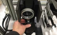
The final assembly area of the Dell is virtually tool-free. To assemble a customized Dell PC, an operator picks up a requested component, slides it along rails into the bay on the chassis, and snaps the rail tabs in place. After a few more seconds spent plugging in a pre-installed cable, the operator selects the next component and repeats the process. Motherboard installation involves picking up the board by the tempan and snapping it into place. Assembly time is reduced by 25 percent to 40 percent, depending on the configuration of the PC. Stimson points out other pluses besides shortened assembly time. "We’ve had a tremendous drop in cosmetic damage to PCs, because we have fewer tools and fixtures to hit the chassis or interfere with the motherboard. We also have fewer screws in inventory, fewer fixtures in the build cell and less tool maintenance," he says. In addition, the different sizes of chassis designs use common plastic and metal parts, reducing inventory and tooling expenses. The integrated cabling in the chassis offers a similar drop in purchasing, storing and kitting. It also augments the freight savings from the reduced packing box size. The cabling arrives shipped in the chassis container, saving inbound freight costs. The parts integration also saves labor and floor space in the kitting area. Finally, because all of these features are common across all three desktop product lines, Dell has been able to standardize its assembly training worldwide. Overall service time for PCs is reduced by 20 percent to 30 percent. Replacement motherboards are delivered from suppliers with tempans already in-stalled. The other components arrive with rails in place. A service call involves tool-less entry and part installation. Dell still uses four screws in one area of in-plant assembly. Because hard drives become obsolete rapidly, it was not practical for Dell to purchase a large inventory of hard drives with the rails pre-installed. Operators in the build cell use torque-controlled nut drivers to fasten rails onto the hard drives. Two screws per rail are used. Minimum time for fitting hard drives with rails is 32 seconds. Cutting those 32 seconds is a good place to start when the time comes to design the next generation of chassis. "We are exploring an automated system for rail installation," says Stimson. "The more we optimize our design, the more we see potential for radically rethinking our processes. As our old products reach end-of-life, we have opportunities to change manufacturing processes for substantial innovation and even more assembly time reductions."


