Friction Stir Welding Expands Its Reach
Originally developed for joining aluminum, friction stir welding is now being applied to other materials, including steel, copper, titanium and even nylon.
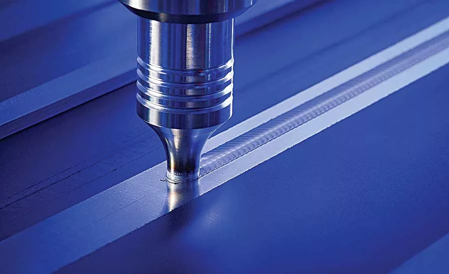
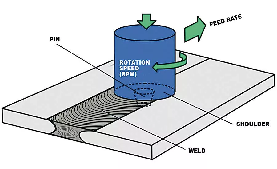
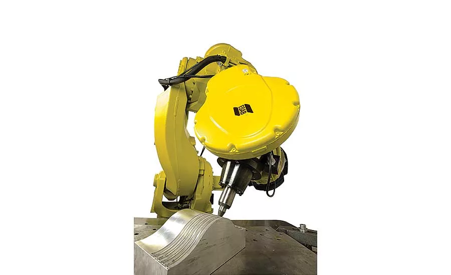
In friction stir welding, a cylindrical shouldered tool with a profiled pin is rotated at high speed and plunged into the joint area between two abutting metal plates. Frictional heat causes the metal to soften without melting. Then, the rotating tool traverses along the joint line, transferring the softened material around itself as it moves. Photo courtesy RWTH Aachen University
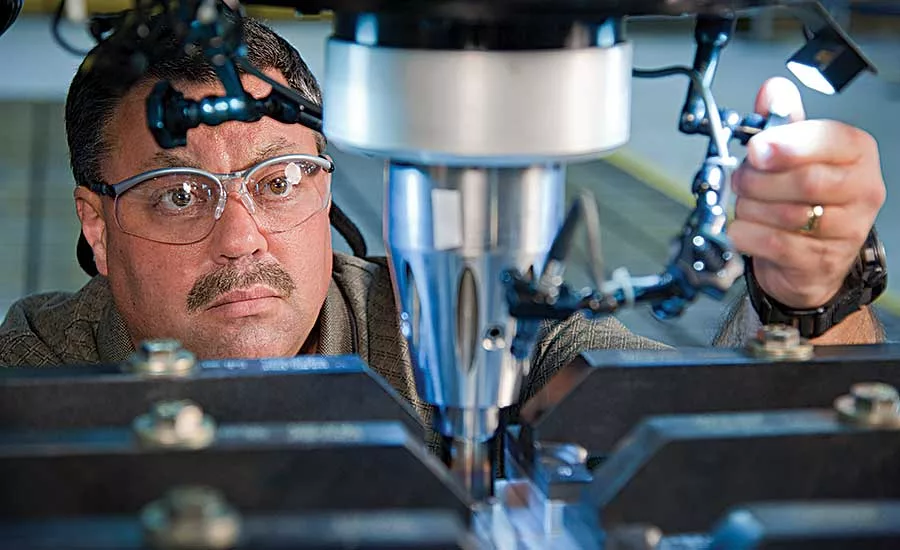
Tim Livengood, a welding engineer with The Boeing Co., confirms the setup on a friction stir weld test fixture. Photo courtesy The Boeing Co.
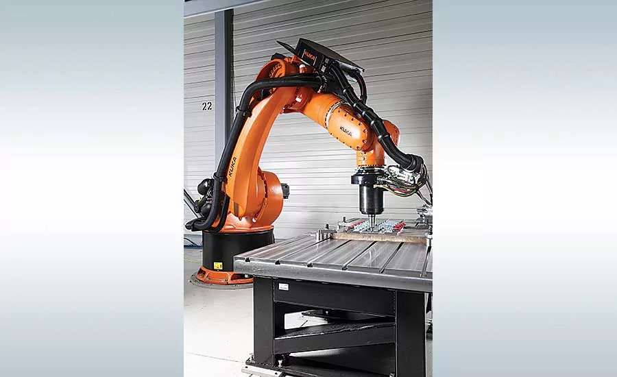
Friction stir welding can be performed by an XYZ gantry machine (if the joint line is on one plane) or a six-axis robot (for three-dimensional joint lines). Photo courtesy Kuka Robotics Corp.
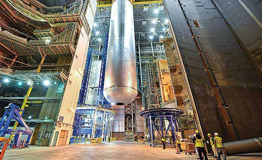
Friction stir welding was used to assemble the liquid oxygen fuel tank of NASA’s new SLS deep-space rocket. Photo courtesy NASA
When it’s finished, NASA’s massive new Space Launch System (SLS) rocket will be truly awe-inspiring.
Designed to carry crew and cargo on exploration missions to deep space, including Mars, the Block 1 configuration of the rocket will have a liftoff weight of 5.75 million pounds, comparable to eight fully loaded 747 jets. It will stand 322 feet high, making it taller than the Statue of Liberty. It will be able to carry 9,000 to 22,000 cubic feet of cargo and have a payload capacity of 154,000 pounds. At liftoff, the rocket will produce 8.8 million pounds of thrust, more than 31 times the total thrust of a 747 jet and 15 percent more thrust than the Saturn V. The rocket will be able to go from zero to 17,500 miles per hour in a little more than 8 minutes after liftoff.
On Sept. 1, NASA finished welding the rocket’s liquid oxygen tank, one of five major components of the 212-foot-tall core stage of the SLS. The other four are the engine section, liquid hydrogen tank, intertank and forward skirt. The liquid hydrogen and liquid oxygen tanks will hold 733,000 gallons of propellant to power the stage’s four RS-25 engines.
Made of an ultra-lightweight, high-strength, low-density aluminum-lithium alloy, the tank cannot be assembled with conventional fusion welding techniques. There are simply too many process factors that must be controlled, such as purge gas, voltage and amperage, wire feed, travel speed, shield gas and arc gap. Instead, the tank was assembled with a relatively new technology: friction stir welding.
Invented in 1991 by The Welding Institute, an engineering research center in the United Kingdom, friction stir welding is different from conventional fusion welding techniques. It does not require an electrical arc, filler material or shielding gas. It does not generate harmful gases, slag or spatter.
In friction stir welding, a cylindrical shouldered tool with a profiled pin is rotated at high speed and plunged into the joint area between two abutting metal plates or sheets. The parts must be securely clamped to prevent the joint faces from being forced apart. Frictional heat between the wear-resistant welding tool and the workpieces causes the latter to soften without reaching their melting points.
Then, the rotating tool traverses along the joint line, transferring the softened material around itself as it moves and stirring material from each part together. The plasticized material is pressed downwards by the tool shoulder, preventing the material from flowing out from the joint line. The material is transported from the front of the tool to the trailing edge where it is forged into a joint. On cooling, a solid-phase bond is created between the workpieces.
Looking for quick answers on assembly and manufacturing topics? Try Ask ASM, our new smart AI search tool. Ask ASM
Friction stir welding is most often used to create butt joints. For butt welds of thin plates, a cylindrical tool is employed, whereas a conical tool is used for butt welds of thicker plates. Whether cylindrical or conical, the tool surface is threaded. The length of the tool closely matches the thickness of the workpieces.
Lap joints are also possible. However, the tool must be modified to ensure full disruption of the oxide layer on the part surfaces. The tool also creates a wider stir zone than butt welding.
Although friction stir welding was originally developed for aluminum alloys, it has also been used successfully for aluminum-lithium alloys, 7075 aluminum alloy and 0.8-millimeter thick zinc plates, which are difficult or impossible to weld through conventional welding methods. The method can also be used to weld magnesium, copper, titanium, aluminum alloy matrix composites, lead, steels and stainless steels. It can also be used to for mixed-material assemblies, such as aluminum to magnesium, carbon steel to aluminum, copper to stainless steel, and nickel alloy to steel.
Friction stir welding can be used on castings, forgings, extrusions and wrought material. Material thicknesses from 0.5 to 65 millimeters can be welded from one side at full penetration, without porosity or internal voids.
It can even be used to weld thermoplastics. Last June, researchers at Universiti Teknologi Petronas in Malaysia demonstrated that friction stir welding could be used to butt-weld plates of nylon 6 up to 16 millimeters thick. The researchers found that, due to its low melt viscosity, nylon 6 is weldable only at lower rotation rates. A tool rotation speed of 300 rpm and a travel speed of 25 millimeters per minute provided good weld results at a 0-degree tool angle. At higher rotation rates, excessive material was squeezed out of the joint line, and defects formed in the weld zone. A tool with a small-diameter shoulder reduced the amount of flash created by reducing the amount of heat input in the joint.
On the other hand, the researchers found that the tensile strength of the welds was quite lower than that of the base material. During tensile tests, all specimens fractured at the interface of the weld zone on the retreating side. This can be attributed to the lack of bonding at the interface of the weld zone on the retreating side, and low crystalline content in the retreating side region.
Compared with conventional fusion welding processes, friction stir welding offers numerous advantages:
- The process can weld 2XXX and 7XXX series aluminum alloys and aluminum-lithium alloys, which are difficult to weld with conventional methods.
- Heat input during welding is lower, so the materials lose less of their mechanical properties.
- Shrinkage, distortion and residual stresses are very small especially in thin plates.
- Surface preparation prior to welding is not too critical. Thin oxide films are tolerated.
- Because it is a solid-state welding process, problems encountered in conventional fusion welding methods, such as cracking and porosity formation, are not experienced.
- There is no need for filler material, shielding gas or other consumables.
- After welding, there is no need for further surface treatment, since it produces clean surfaces.
- One tool can typically produce as much as 1 kilometer of weld joints.
- The process is environmentally friendly. There is no emission of gas, dust or electrical arcs.
- It is highly energy efficient.
- The process also has some disadvantages:
- It can only be applied to materials with low strength and low melting point. Higher melting point materials require special tools.
- The parts to be welded must be fixed firmly.
- The speed of welding is relatively low, typically 750 millimeters per minute for 6XXX series aluminum alloy plates 5 millimeters thick.
- Powerful machines are needed for joining thicker plates.
Friction stir welding is being used in myriad applications, including ships, trains, cars, heavy trucks, military vehicles, airplanes, spacecraft and medical equipment. The process isn’t restricted to monolithic structures, either. Parts of Apple Inc.’s iMac are assembled with friction stir welding.
Process Parameters
The main variables of the friction stir welding process are welding (travel) speed, tool rotation speed, axial force on the tool, the tilt angle of the tool, and tool design. These variables determine the peak weld temperature, linear force, torque and power.
Peak weld temperature increases significantly as tool rotation speed increases and decreases slightly as travel speed increases. Weld temperature also increases with as axial pressure increases. Axial pressure also influences joint quality. High pressures lead to overheating and thinning of the joint, while low pressures may lead to insufficient heating and, in turn, void formation.
Higher travel speeds may cause excessive linear force, which may, in turn, lead to tool erosion and even tool breakage. The power requirement also increases as axial pressure increases.
The torque depends on several parameters, such as axial force, tool design, tilt angle, local shear stress at the tool-workpiece interface, the friction coefficient, and the extent of slip between the tool and workpiece. The torque decreases with an increase in tool rotational speed, owing to an increase in peak temperature. On the other hand, torque is not significantly affected by a change in travel speed.
The peak temperature is not significantly affected by travel speed. High travel speeds tend to reduce heat input applied to the workpieces during friction stir welding. Therefore, the torque increases only slightly with increasing travel speed, since material flow becomes somewhat more difficult at slightly lower temperatures.
Welding Machines
Friction stir welding can be performed by an XYZ gantry machine (if the joint line is on one plane) or a six-axis robot (for three-dimensional joint lines).
For example, the LEGIO from ESAB Welding and Cutting Products is a gantry-style machine. The X and Y axes consist of heavy-duty bearings and ballscrew linear actuators. The weld head has a travel range of 1 to 5 meters. The Z axis is hydraulically actuated.
The rotating spindle is driven by an AC motor. Liquid cooling is provided to minimize the wear on the spindle components and the pin tool.
A PLC provides precise control over speed, force and positioning.
Alternatively, friction stir welding can also be done by a six-axis robot, such as ESAB’s Rosio. The cell consists of an ABB IRB 7600 robot, modified for the purpose of friction stir welding. The welding equipment is integrated in the mechanical structure of the robot without limiting the robot’s standard working envelope. The robot’s work envelope spans more than 2.5 meters. The robot can apply as much as 13 kilonewtons of downward force during welding.
Variations on a Theme
There are several variations of friction stir welding.
In reverse dual-rotation friction stir welding, the tool pin and the shoulder are separated and rotate in opposite directions independently, so that there are actually two material flows in the weld joint. The process is said to significantly improve microstructure and properties of the weld joint.
Another variation is laser-assisted friction stir welding. In this method, a laser beam is used to preheat the parts immediately ahead of the rotating tool. The laser introduces additional local heating so that less mechanical energy from the tool must be converted into heat. This reduces the linear and axial forces exerted on the tool, decreases deflections in the machine and fixture, and may enable faster weld speeds. It also enables the process to be used to weld difficult materials, such as titanium; mixed materials; and steels, which have higher melting temperatures than aluminum.
In friction stir spot welding, the rotating tool is plunged and retracted, but not traversed (see ASSEMBLY magazine, April 2016). This method is particularly advantageous for joining aluminum sheet metal parts in automotive applications. In many cases, it can be readily substituted for resistance spot welding with little or no design modifications.
One more variant of friction stir welding is friction stir processing. No parts are joined with this technique. Rather, the tool is simply traversed through a single piece of material to enhance its material properties. In castings, the technique can be used to eliminate porosity. In other applications, the material can be processed to improve the ductility of the material.
Looking for a reprint of this article?
From high-res PDFs to custom plaques, order your copy today!


