Double-Pulse Ultrasonic Welding of Fiber-Reinforced Composite
Photo courtesy Prusa Polymers
Ultrasonic welding is widely used to join polymers because it is fast, economic and suitable for mass production. This technique joins parts through friction and viscoelastic dissipation in the polymer.
The parts to be welded often have a small initial contact at the joint interface to concentrate the ultrasonic energy and initiate melting. For many applications, this small contact area is achieved with an energy director, a sharply pointed triangular rib molded onto the surface of one of the parts. But, because creating this feature can increase the cost of the parts, research has focused on ways to weld parts, particularly polymeric composites, without energy directors.
When welding polymers without an energy director, the energy is not concentrated, and coulombic friction at the faying interface is less than that of a joint with an energy director. As a result, the parts need more time to melt, and overall welding time is longer. However, thermoplastics produce viscoelastic dissipation under ultrasonic welding, which leads to an increase in part temperature with the extension of weld time. When the temperature rises above a certain point, thermal decomposition of the polymer will occur and a porous region will form, which severely deteriorates weld quality.
One way to get around this problem is to heat the parts prior to welding. Heat generation during ultrasonic welding depends on the loss modulus of the polymer, and the loss modulus is closely related to the temperature of the parts. Thus, preheating the parts can shorten weld time and decrease the risk of thermal decomposition. The problem with this solution is that it requires an extra operation and it has limited effect.
We have developed an alternative solution: double-pulse ultrasonic welding. In our technique, the first pulse is used to preheat the parts, while the second completes the weld. The first pulse generates heat at the joint interface. The materials at the interface melt first, and the temperature is higher there than in the middle of the workpiece. After cooling for a while, another ultrasonic pulse is applied at the same location to extend the size of the weld. The temperature in the middle of the workpiece is maintained below the decomposition temperature of the plastic by adjusting the weld time and cooling time between the two pulses. As a result, weld quality is improved by increasing energy dissipation at the joint interface while inhibiting thermal decomposition.
In this study, we tested our technique on carbon-fiber-reinforced polyamide 66 (CFPA 66). Our goal was to determine the relationship between the loss modulus of the material, the time needed to obtain a good weld, and the time for decomposition to occur.
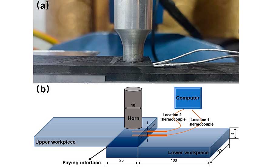
To analyze weld formation, temperature evolutions near the joint interface and in the middle of the upper part were measured. Two thermocouples were embedded into upper part for this purpose. Source: Hunan University of Science and Technology
Materials And Experimental Procedure
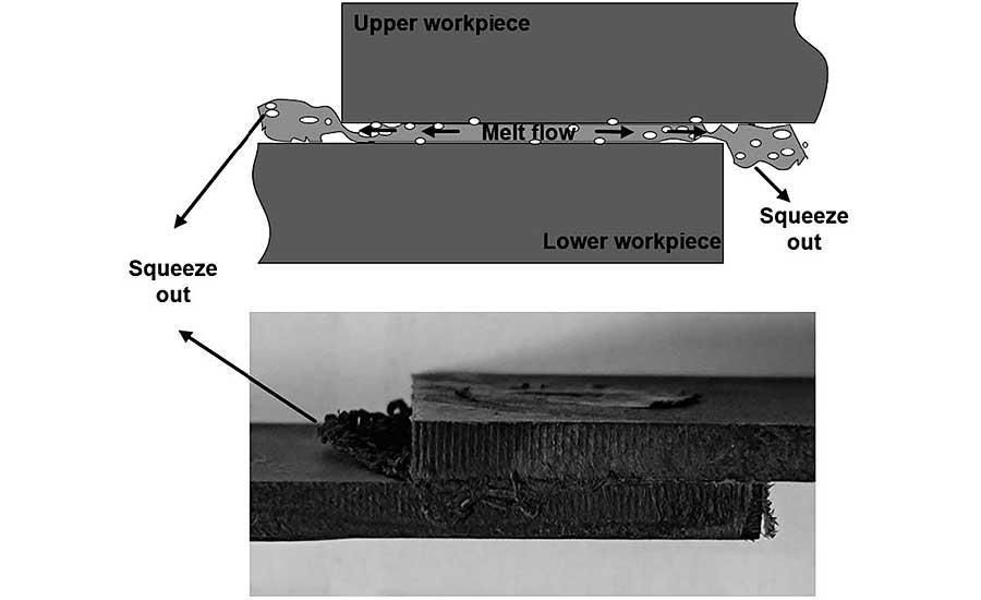
The optimal preheating temperature depends on the temperature in the middle of the upper part, because most of the decomposed material at the joint interface will be squeezed out and flow bilaterally under weld pressure. Source: Hunan University of Science and Technology
There are two heating systems in ultrasonic welding of polymer composites: surface friction and viscoelastic dissipation. During welding, it only takes a few seconds to create a weld, and state transformation does not take place. Therefore, the initial loss modulus at the very beginning of welding is the loss modulus of CFPA 66 during welding. The loss modulus increases initially and then decreases. The peak value occurs at around 75 C.
Looking for quick answers on assembly and manufacturing topics? Try Ask ASM, our new smart AI search tool. Ask ASM
While prolonging weld time creates a larger weld area—and thus, a stronger joint—too much weld time leads to thermal decomposition of the polymer. The goal of our study was to determine the amount of time that creates the strongest weld (ts) and the amount of time that leads to thermal degradation (td).
Generally, ts and td decrease as the preheating temperature rises. Peak values occur at approximately 75 C, which is likely correlated with the preheating temperature and corresponding loss modulus of the parts.
The decreases in ts and td are mainly because preheating provides energy for weld formation and part decomposition. The peak and valley located at 75 C are present because the maximum loss modulus of CFPA 66 is at this temperature. The larger loss modulus leads to higher energy dissipation in the parts and relatively lower heat generation at the joint interface. Therefore, the time for obtaining a strong weld increases, and the time for thermal decomposition decreases.
This graph shows the loss modulus of CFPA 66 composite at 20 kilohertz (black curve) as a function of temperature. The loss modulus increases initially and then decreases. The peak value occurs at around 75 C. Source: Hunan University of Science and Technology
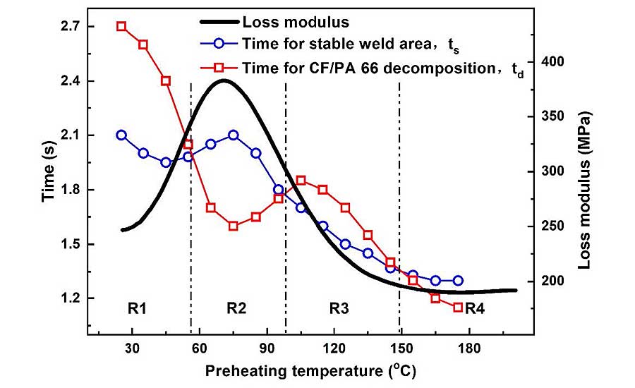
We plotted the loss modulus curve for our polymer against the time curves for creating a strong weld and for polymer decomposition in Figure 2. Three intersections are observed, and the whole range is divided into four regions: R1, R2, R3 and R4.
In R1 and R3, ts is smaller than td, implying the joint achieves its maximum weld area before thermal decomposition occurs. Accordingly, R1 and R3 are the appropriate regions, and ts is the proper weld time for joints with preheating temperatures ranging from 25 to 55 C and from 95 to 145 C.
In regions R2 and R4, ts is larger than td, indicating the composite decomposes before the joint obtains a stable weld area. Assuming the plastic does not decompose, then the weld area of the joint is smaller, and the joint strength is lower. Consequently, the R2 and R4 regions should be avoided when welding CFPA 66 without energy directors.
In practical production, ultrasonic welding is usually done at room temperature (25 C), which lies in R1. According to the curve, then, the corresponding optimal weld time would be 2.1 seconds for the first pulse.
Once the weld time for the first ultrasonic pulse is determined, the cooling interval between two pulses must be ascertained. Since preheating temperature is closely related with weld quality, the temperature before application of the second pulse should be in the range of R1 and R3.
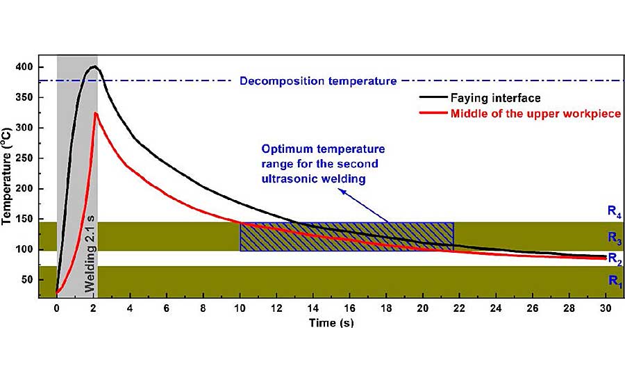
This graph shows the transient temperature evolutions at the joint interface and the middle of the upper part during welding. The temperatures at both positions show similar tendencies, which increase during welding and then decrease after vibration stops. The R3 region (95 to 145 C) is the most suitable initial temperature for the second pulse. Source: Hunan University of Science and Technology
Figure 3 shows the transient temperature evolutions at the joint interface and the middle of the upper part during welding. The temperatures at both positions show similar tendencies, which increase during welding and then decrease after vibration stops. Notice that R1 is in the range of 25 to 55 C, and it takes a long time for the joint to cool down, which is not efficient for manufacturing. The R3 region (95 to 145 C) is therefore the most suitable initial temperature for the second pulse.
The optimal preheating temperature depends on the temperature in the middle of the upper part, because most of the decomposed material at the joint interface will be squeezed out and flow bilaterally under weld pressure.
It takes about 8 seconds for the middle of the upper part to cool to the R3 region. Considering the temperature gradient in the upper part and ensuring that the temperature of the entire upper part lies in the range of R3, we adopted an interval time of 12 seconds between the two ultrasonic pulses. We selected 1.5 seconds as the weld time for the second pulse.
In summary, our double-pulse method consisted 2.1 seconds for the first pulse, 12 seconds of cooling time, and 1.5 seconds for the second pulse.
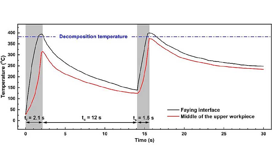
This graph shows the temperature histories at the joint interface and the middle of the upper part. The latter is always lower than that at the interface. It is also clear that the temperature in the middle of the upper part is lower than the decomposition temperature of CFPA 66. Source: Hunan University of Science and Technology
Mechanical Properties Of The Joint
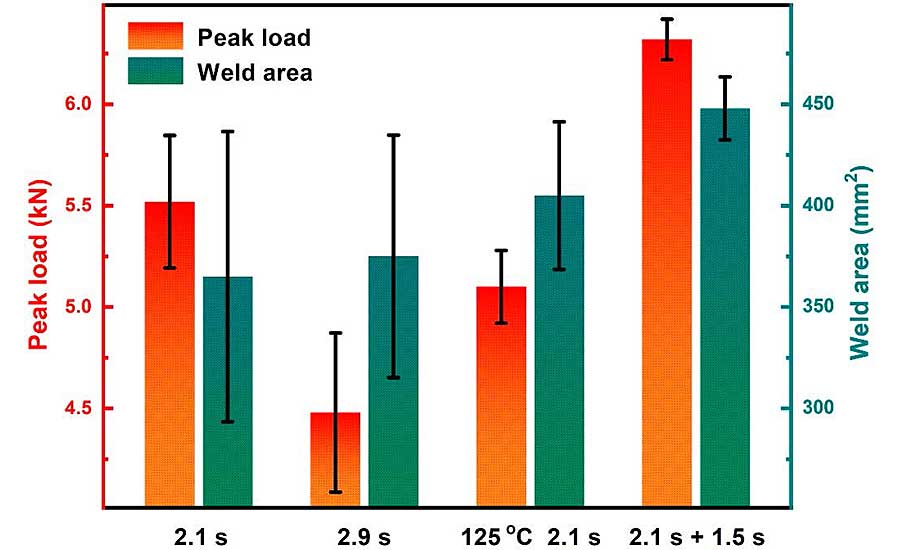
This graph compares the peak loads of joints welded with different weld parameters: a single weld of 2.1 seconds; a single weld of 2.9 seconds; a single weld of 2.1 seconds with the parts preheated to 125 C; and our double-pulse technique. The double-pulse technique created the largest and strongest joint. Source: Hunan University of Science and Technology
Figure 6 compares the peak loads of joints welded with different weld parameters: a single weld of 2.1 seconds; a single weld of 2.9 seconds; a single weld of 2.1 seconds with the parts preheated to 125 C; and our double-pulse technique. The double-pulse technique created the largest and strongest joint.
Similarly, examination of the fractured surfaces of the joints revealed differences between the techniques (Figure 7). The joint created by the single weld of 2.1 seconds is roughly circular in shape and contained no obvious porous areas. The joint created by the single weld of 2.9 seconds is slightly larger, but has an obvious porous area, which led to much lower joint strength.
Looking at the joint created by a single 2.1-second weld of preheated parts, the weld area was larger than that created by a 2.1-second pulse without preheating, but the joint strength was actually lower.
The joint created by the double-pulse technique is 23 percent larger than the joint created by a single 2.1-second pulse. This indicates that our double-pulse technique increased energy dissipation at the joint interface. The parts were not overheated, and no porous area occurred in the joint.
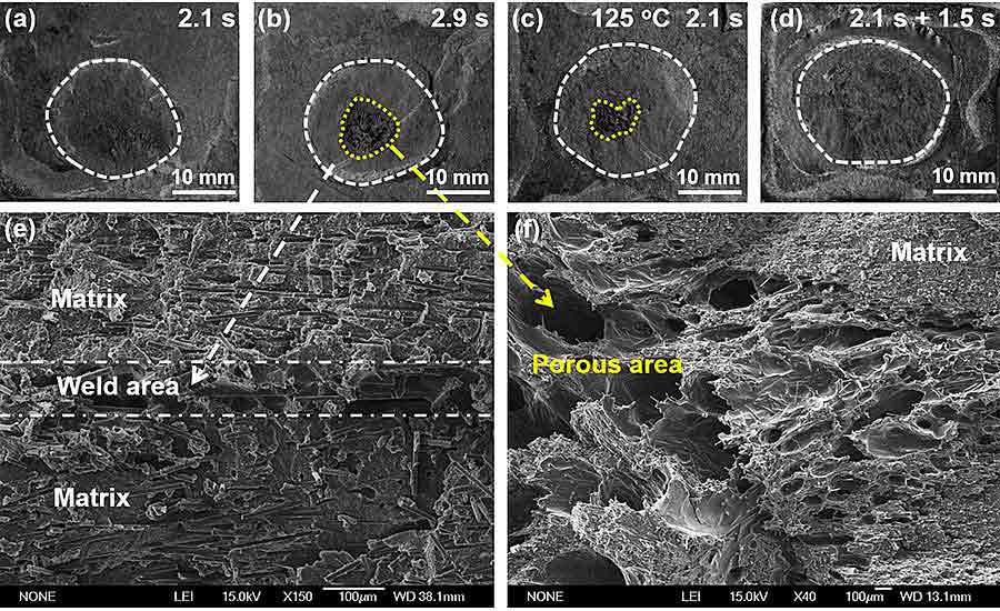
Examination of the fractured surfaces of the joints revealed differences between the techniques. For example, the joint created by a single weld of 2.9 seconds is large, but has an obvious porous area, which led to much lower joint strength. Source: Hunan University of Science and Technology
It’s worth noting that the double-pulse process not only improves weld quality, but also decreases the variance in peak load, which is beneficial for producing continuous solid joints. This is likely correlated with the contact condition at the joint interface. It is difficult to guarantee absolute flatness of the parts during manufacturing. Thus, the contacts between parts differ at the initial stage of welding. Surfaces with higher asperities usually generate more heat and obtain intimate contact between the parts.
By contrast, heat generation becomes limited for joints with loose contact and results in insufficient welds. However, the asperities melt and solidify after application of the first ultrasonic pulse, which results in a relatively flat joint interface. Thus, the second pulse can be evenly distributed at the joint interface. A stable weld seam is obtained, and the spread in peak load narrows.
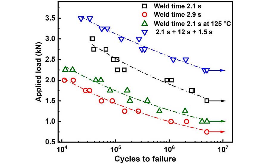
This graph shows the relationship between stress and the number of cycles to failure for our test joints. The fatigue life of double-pulse welded joints is significantly higher than that of the preheated and single-pulse welded joints. Source: Hunan University of Science and Technology
Fatigue life is important, because the joint will inevitably experience complex and repeated mechanical loading during service. Figure 8 shows the stress vs. number of cycles to failure curves for our test joints. The fatigue life of double-pulse welded joints is significantly higher than that of the preheated and single-pulse welded joints.
There are three possible reasons for the improvement in fatigue life. First, the weld strength of joint is higher. Second, the residual heat from the first vibration preheats the parts before application of the second pulse, which reduces the temperature gradient between weld seam and matrix and thus decreases residual stress in joint. Third, the problem of insufficient welds caused by the surface roughness of the parts is eliminated, and the stability of the joints is improved.
Editor's note: The following people also contributed to this report: Yongbing Li, Shanghai Jiao Tong University, Shanghai, China; Peng Shu, Hunan University of Science and Technology; Xinrong Tan, Hunan University of Science and Technology; Caiwang Tan, Harbin Institute of Technology, Weihai, China; and Zhongxia Liu, Zhengzhou University, Zhengzhou, China.
MORE FROM ASSEMBLY ONLINE
For more information on composites assembly, read these articles:
Spot Welding Metal-Plastic Composites
Effects of Plasma Treatment on Bonding CFRP
Automating Carbon-Fiber Composite Fuselage Assembly
Looking for a reprint of this article?
From high-res PDFs to custom plaques, order your copy today!


