Spot Welding Metal-Plastic Composites
A new resistance spot welding process can join metal-plastic composites
Metal-plastic composites (MPCs) have many advantages for producing lightweight structures. They are lighter than steel, yet very strong. They can be shaped using standard cold-forming processes. And, they are less expensive than aluminum alloys.
One problem that has prevented wider implementation of these materials has been a lack of technologies for joining MPCs with each other as well as with other materials, such as steel and aluminum. Conventional thermal joining techniques, such as arc welding or laser welding, are not applicable due to the presence of the polymer layer. Alternative technologies, such as clinching or blind riveting, cannot create high-quality joints.
Currently, MPCs are joined by mechanical fasteners, such as self-piercing rivets; forming, such as hemming and seaming; and adhesive bonding. However, these methods have some disadvantages. Mechanical fasteners can create stress concentrations and delamination during machining. Forming processes are complex and expensive, and they cannot create lap joints. Adhesive bonding requires extensive surface preparation and long curing times.
Due to the limitations of thermal joining of MPCs, researchers have tried some novel approaches to joining these materials. For example, one technique involves using mechanical nuggets to produce lap joints in MPCs. The process involves drilling a blind hole and removing the upper metal cover sheet and the polymer core. Then, the MPC sheets can be joined together by compressing a metal insert placed in-between. Other researchers have tested friction stir welding and hybrid joints involving clinching and adhesives.
Resistance spot welding (RSW) is a fast and well-established method for joining sheet metal. Thus far, however, it has been challenging to use the technique to join MPCs due to the presence of the nonconductive polymer layer. Previous research has shown that spot welding MPCs is not possible without modifying the joint—either by removing small amounts of polymer to achieve electrical contact between the two metal layers or by introducing an additional heating element into the matrix.
For example, in one experiment, researchers placed a stainless steel mesh at the interface between carbon-fiber-reinforced polyetherimide and aluminum sheets. When resistance welding was used to join the combined materials, the joints had a lap shear strength greater than 20 megapascals (MPa). On the other hand, the large amount of heat applied to the joint caused significant motion and deconsolidation of the fibers. Subsequent research showed that joint strength could be improved by modifying the surface of the aluminum or adding a silane coating to the stainless steel mesh.
We decided to further explore the viability of spot welding for joining MPCs to steel. Specifically, we examined three techniques: shunt-current-assisted RSW, induction-heating-assisted RSW and ultrasonic-assisted RSW.
Looking for quick answers on assembly and manufacturing topics? Try Ask ASM, our new smart AI search tool. Ask ASM
Materials and Equipment
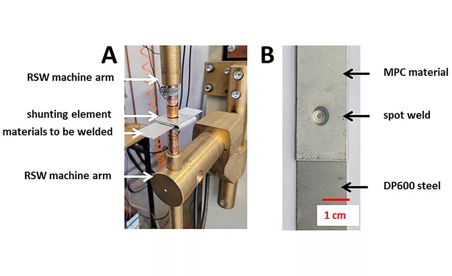
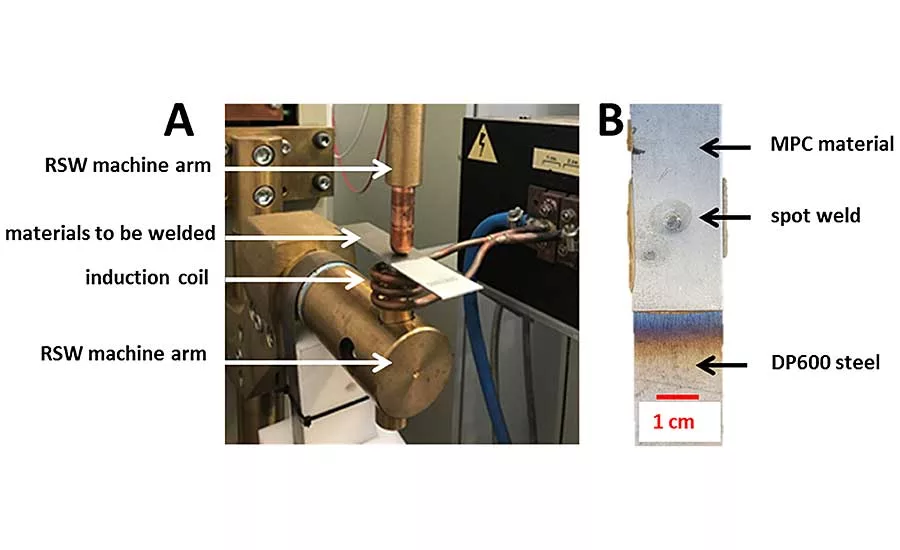
In our experiments, we used RSW to join Litecor to DP600 sheet steel.
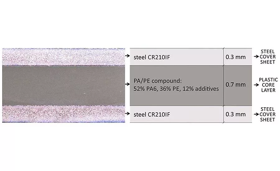
Litecor is a sandwich material made by ThyssenKrupp Steel Europe. Litecor is a compromise between steel and aluminum in terms of weight and economy. It has a tensile strength of 190 to 240 MPa and a yield point 120 to 180 MPa. It consists of three layers created through a warm roll-bonding process. The outer layers are made of HX220YD steel, 0.2 to 0.5 millimeter thick, with a zinc coating for corrosion protection. The inner layer is a mix of polyamide and polyethylene, 0.3 to 1 millimeter thick. It has a melting temperature of 220 C, a solidification temperature of 192 C, and a decomposition temperature above 300 C.
The DP600 sheet is 0.8 millimeter thick. DP600 is a two-phase steel containing soft ferrite for good formability and hard martensite for high strength. It is a cold-rolled steel with a formability that makes it suitable for deep-drawn components. It has good weldability and is suitable for car safety components.
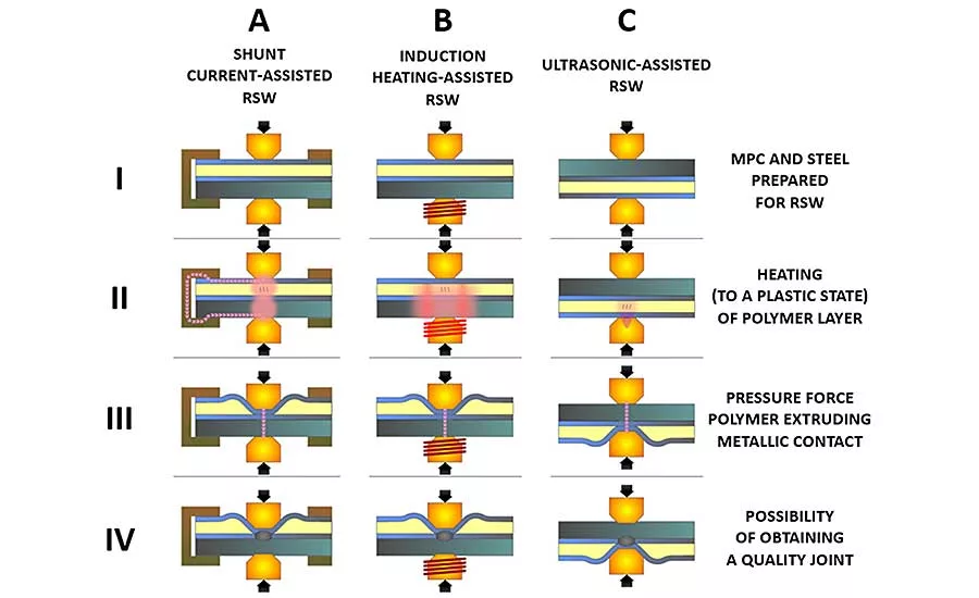
The biggest limitation to spot welding of MPCs is the presence of a nonconductive core, which limits (or even prevents) the flow of electric current through the material. To ensure the current flow through the external metal sheets, the nonconductive polymer must be removed in the first stage of the process.
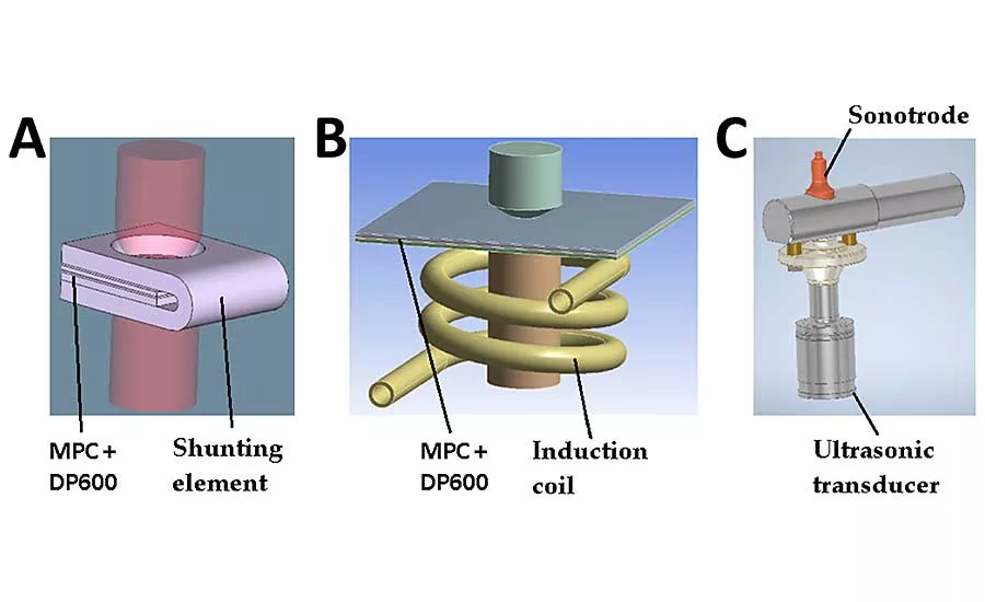
In shunt-current-assisted RSW, current flows through the circuit with lower resistance—a shunt element made of aluminum—and bypasses the polymer layer. The heat generated in the shunting element is transferred into the external metal cladding of the MPC, which in turn heats the polymer core. Pressure from the electrodes pushes the molten polymer aside, enabling the metal sheets to contact each other so a spot weld can be created. The shunt element is a flat bar of aluminum, 3 millimeters thick, bent at a 180-degree angle.
In induction heating-assisted RSW, the bottom electrode of the spot-welding gun is overlapped by an induction coil. The welding process occurs in two stages. The inductor is switched on first. The magnetic field generated by the coil causes eddy currents to flow through the bottom electrode and the DP600 steel. The heat generated in the steel is transferred into the MPC. After a set amount of time, the inductor is turned off and resistance welding occurs. The heat generated by the coil melts the polymer, which is squeezed from the joint under pressure from the electrodes. Thus, current is able to flow and a spot weld can be formed. For induction heating, a high-power inductor (40 kilowatt, 22.5 kilohertz) was used. The coil consists of three turns of copper pipe, 5 millimeters in diameter. Each coil has an internal diameter 45 millimeters.
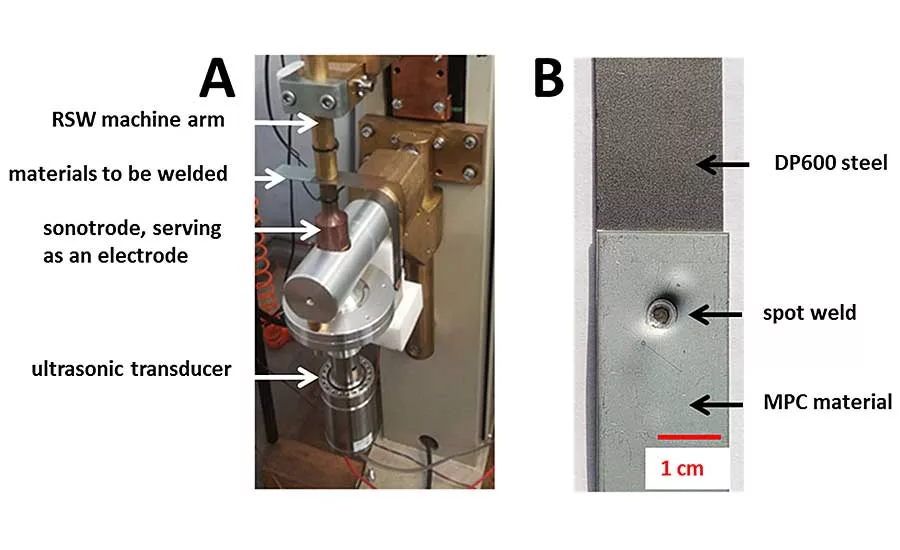
Ultrasonic-assisted RSW combines two physically different ways of heating the materials. In the first phase, the polymer core is heated by high-intensity ultrasonic waves, and the melted polymer is forced from the joint by pressure from the electrodes. In the second phase, the welding current is switched on and the spot weld forms as normal. In this approach, the lower electrode does double duty, serving has both an electrode and an sonotrode with a frequency of 20 kilohertz and a maximum power of 3 kilowatts.
In each of these three processes, the resistance welding is done by a 10-kilohertz resistance spot welding gun with a power of 40 kilovolt-amps and a force range of 0.8 to 4.5 kilonewtons.
We used finite element modeling (FEM) to determine the various parameters for each welding process.
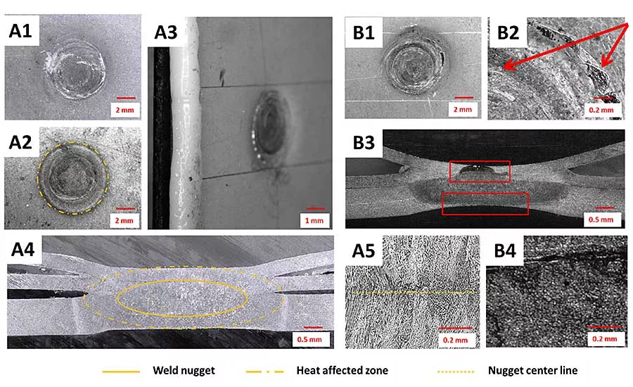
To assess the welds, we conducted microscopic examinations of cross-sections of the weld nuggets, looking at morphology, the heat-affected zone, and the overall quality of the weld.
Shunt-Current-Assisted RSW
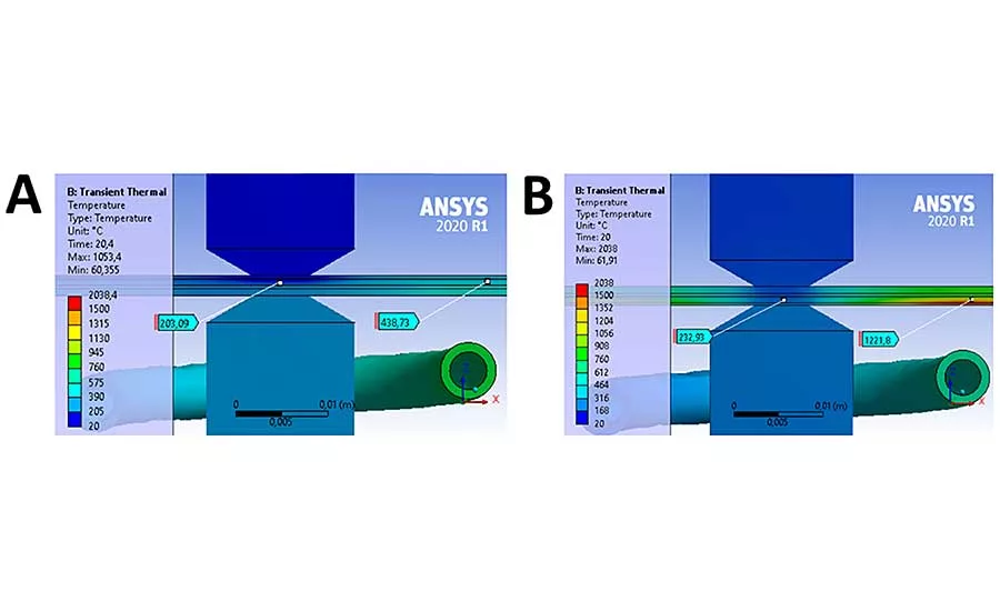
Our FEM analysis showed that heating the materials too rapidly caused a strong degradation of the metallic cover sheets of the MPC. The upper MPC outer layer was overheated, deformed, and the entire MPC delaminated. This is because of the high electrical resistance of the polymer, its low thermal conductivity, and the inability to quickly dissipate heat out of the welding area. In addition, the high welding current applied in one pulse caused a strong degradation of the cover material, while the polymer layer did not reach the appropriate temperature to be removed from the welding zone.
In practice, we solved the overheating problem by using a multi-pulse welding program that consists of five to 10 preheating pulses with a small current value (3 to 4 kiloamps). Then, after forming the polymer core, a final high-intensity current pulse (6 kiloamps) was applied. This ensures a longer heating time, but a more uniform temperature distribution in the welding zone. In this way, it is possible to prevent thermal degradation of the MPC and obtain a high-quality weld. The entire process takes approximately 5 seconds.
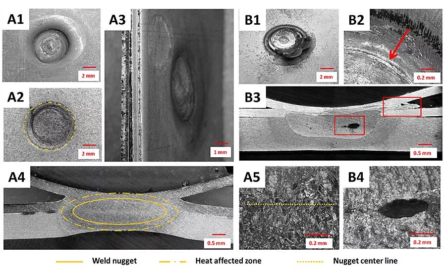
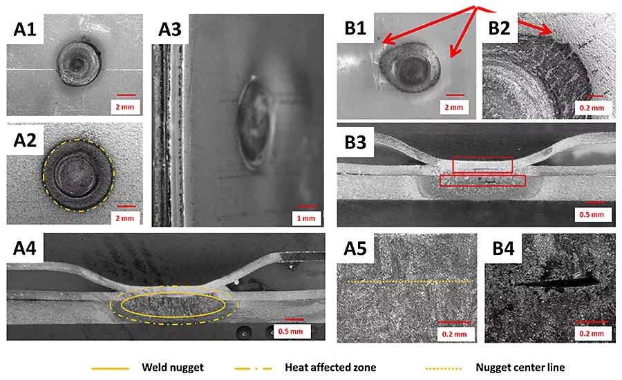
The diameter of the welds was around 3.9 millimeters. The joints did not show cracks in the outer metallic layer or visible polymer expulsions. Examination of the weld cross-section revealed a properly established nugget, which included three layers of metal sheets and was not contaminated by the polymer core.
However, different non-conformities and defects were also observed. Cracking of the outer metal sheet and extensive polymer expulsion were observed at the spot-weld surface when the process parameters were not properly set. This was usually observed when too long or too intensive heating of the shunt current was set. In some cases, this even caused burning of the polymer layer and a poorly formed weld nugget.
Shunt-Current-Assisted RSW
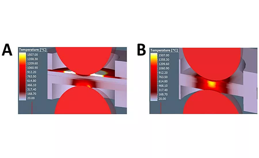
Our FEM investigation indicated that the inductor is best located on the solid-steel side of the joint, rather than the MPC side, since the steel sheet acts as a thermal buffer.
Locating the inductor on the MPC side results in rapid heating. The top sheet reached about 1,500 C after just 20 seconds of heating, while the polymer reached the plastic state. This was sufficient to allow the free flow of the polymer from the welding zone. However, it’s worth noting that the polymer reached almost 1,221 C at the edges of the sheets. This led to the charring, burning, disintegration and overall inevitable degradation of the MPC material. Of course, the power used for heating can be reduced, but this prolongs the heating time.
When the inductor is located on the solid-steel side, the cover sheet of the MPC is not overheated and reached a temperature of about 650 C after 20 seconds of heating. The polymer in the welding zone reached a temperature of 203 C, which was sufficient for further processing. There was also no overheating of the polymer at the edge of the sheets, which reached a temperature of about 439 C. This did not lead to the degradation of the polymer or the MPC as a whole.
The welding process was carried out in two stages. In the first stage, the material was preheated by induction. The inductor current was 468 amps, and the heating time was 30 seconds. Next, the welding electrodes were immediately pressed with a force of 2 kilonewtons, and the welding current was turned on. Welding current was 5.5 kiloamps, and the welding time 150 milliseconds.
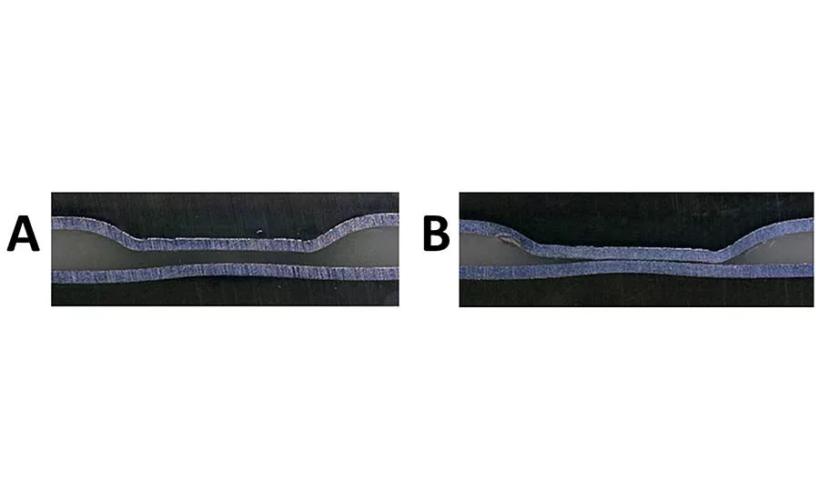
The process produced satisfactory welds. The average diameter of the joints was 4.7 millimeters. There was relatively low indentation depth from both sides and no surface-breaking cracks. However, a quite extensive heat-affected zone was visible, as was outflow from the polymer core. The weld nugget was well formed, comprising all metallic layers. Due to high heat input during the initial stage of the polymer layer removal, the nugget consisted of much coarser grains than nuggets produced by the other concepts. On the other hand, when the welding parameters were overestimated, the quality of each weld dramatically decreased. The external steel cover sheet was deformed or even broken. In some cases, the joint geometry was completely disturbed, resulting from the slip of the MPC cover sheets on the melted polymer core.
Ultimately, this method has potential. However, more extensive research is needed on the preheating process.
Ultrasonic-Assisted RSW
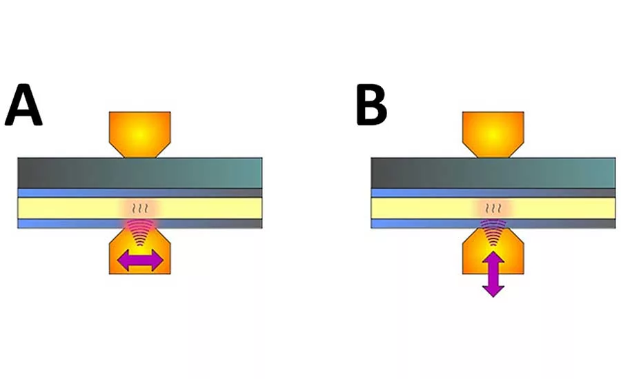
Ultrasonic-assisted RSW was designed to overcome the limitations of the other two methods by shortening the preheating time; reducing the degradation of MPC cover sheet materials; and increasing the quality of the electrical contact of the electrodes with the materials. FEM calculations were aimed at selecting the right vibrations (longitudinal or transverse) to use in the preheating process.
The FEM analysis showed that the most effective heating method was with longitudinal vibrations. The temperature was more concentrated in the welding area than with transverse vibrations. Moreover, this type of vibration ensures the shortest heating time, without unnecessary heating of the steel cover layers. But, when setting the parameters of the process, attention should be paid to the glass transition temperature and the plasticization temperature of the polymer.
Unlike the other two RSW methods, ultrasonic-assisted RSW generates thermal energy inside the polymer layer. As a result, the problem of the low thermal conductivity of the polymer is not significant, and heating time does not have to be extended. This provides significantly more favorable conditions for the removal of the polymer layer from the welding area.
With this method, it’s important to set the ultrasonic parameters to ensure that the polymer is displaced from the weld joint, allowing current to flow for welding. If this is not done, one of two things can happen. One, there will be no welding current, and the joint will not be formed. Or, if some welded joints have already been made, a shunt effect may occur: The entire welding current will flow through the MPC coating. This is a highly unfavorable and dangerous situation. It can lead to overheating, delamination, deformation and even complete loss of material continuity and expansion. The protective coating can also be damaged.
For this reason, it is essential to monitor the polymer removal process and the moment of electrical contact. This can be done by measuring the dynamic electrical resistance during the ultrasonic heating process. Small pulses of welding current are all that is necessary for monitoring. It is also possible to provide feedback to the ultrasonic generator to control when the preheating process is completed and the resistance welding process starts.
In our experiments, we tested three heating times (150 milliseconds, 250 milliseconds and 1 second) and five voltage amplitude levels for the ultrasonic transducer (10 percent, 20 percent, 30 percent, 40 percent and 50 percent). We also looked at the best place to put the ultrasonic transducer: on the solid material side or the MPC side.
The resistance welding process was carried out using a two-pulse welding program. The first pulse was aimed at removing the zinc coating from the surfaces to be joined. It also allowed us to measure the dynamic resistance value to make sure that the welding process can be safely and properly carried out. The second pulse was used to create the weld. The parameters were set to obtain the maximum diameter of the weld nuggets with the shortest welding time and the least amount of imperfections.
The average diameter of the joints was 5.3 millimeters. The weld nugget was properly formed and covered all three steel sheets. The heat-affected zone was very narrow, much smaller than with the two other concepts. Similarly, the grains were small in the central part of the weld nugget. The polymer core was well-removed and heated locally, so the core layer surrounding the spot weld was free of pores and discontinuities. However, this also caused some irregular deformation of the outer layer of the MPC cover sheet. Defects occurred rarely. The most common were a lack of fusion between all metal layers or small shrinkage cavities observed in the center of the weld nugget.
Conclusions
Our research indicates that it is possible to use RSW to join MPC to steel.
When using shunt-current-assisted RSW, design of the shunting element and setup of the process parameters are critical to avoid overheating the materials. To lower the risk of degrading the MPC, a multi-pulse process should be applied. The most common defects are cracking of the outer metal sheet and expulsion of the polymer from the joint. Due to the need to mount the shunting element, it is difficult to use this concept in an automated mode.
Induction heating-assisted RSW was the most effective method for heating the materials in the welding zone. However, proper placement of materials on the inductor is needed to obtain homogeneous temperature distribution and to protect the MPC from rapid and extensive overheating. Nevertheless, a large amount of polymer can be displaced from the core, since a relatively large area is heated at once. As a result, the heat-affected zone is quite extensive. If the induction heating process is too long, the overall quality of the joint dramatically decreases.
Ultrasonic-assisted RSW is the most complex of the three concepts. The type of vibrations strongly influence the heating of materials in the joining zone. The process is very short, so it does not increase overall cycle time and heating is very localized. On the other hand, the process does cause some irregular deformation of the outer layer of the MPC cover sheet next to the joint.
Looking for a reprint of this article?
From high-res PDFs to custom plaques, order your copy today!


