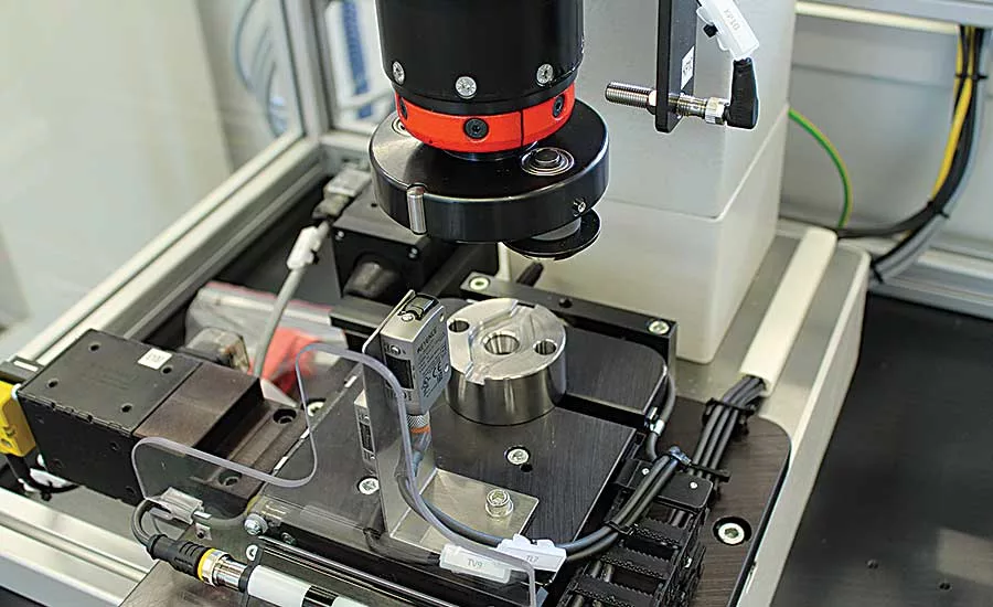
Roller Forming for Cylindrical Assemblies
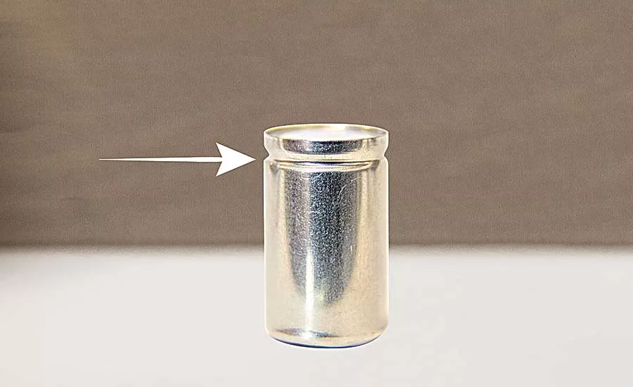
The Roller Forming Process Forms a Curl or Lip on the Edge or Rim of a Hollow, Cylindrical Part
There are many ways to crimp or flare a lip on a cylindrical part. For example, it can be done with a press or an orbital forming machine. However, the problem with those processes, particularly the former, is that they require a good deal of force.
For thin-walled parts, or parts made from less ductile materials, that’s not ideal. For these applications, a third method—roller forming—is an emerging option.
Like orbital and radial forming, roller forming is a nonimpact process for cold-forming metal. However, instead of forming a head on a post or a rivet, the process forms a curl or lip on the edge or rim of a hollow, cylindrical part. This can be done to secure a part, such as a bearing or a cover plate, inside another part, or it can simply be used to finish the ends of a metal tube to make it safer, improve cosmetics or facilitate insertion of the tube into another part.
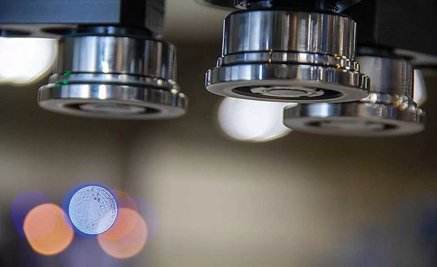
In orbital and radial forming, the head is formed by a peen attached to a rotating spindle that simultaneously exerts downward force on the workpiece. In roller forming, the peen is replaced with multiple rollers. With the head rotating at 300 to 600 rpm, each pass of the rollers gently pushes and smooths the material into a seamless, solid form. In contrast, an orbital forming operation typically runs at 1,200 rpm.
“Orbital and radial are really more appropriate for a solid rivet. This is more for a tubular assembly,” says Tim Lauritzen, product application engineer at BalTec Corp.
The rollers intersect the workpiece on a precise contact line, gradually moving material to the desired shape. The process takes about 1 to 6 seconds.
“[Forming time] depends on the material, how far you have to move it, and what geometry you have to form the material to,” says Bryan Wright, vice president of sales at Orbitform Group. “You have to consider the wall thickness and tensile strength of the tube.”
Looking for quick answers on assembly and manufacturing topics? Try Ask ASM, our new smart AI search tool. Ask ASM
Roller forming can be applied from the top down, from the bottom up, or from the side. The only requirement is adequate clearance for the tooling.
The process can form a variety of materials, including brass, copper, cast aluminum, low carbon steel, high carbon steel and stainless steel.
“Die-cast aluminum is a good material for roller forming, because of the galling that can occur when trying to form it,” says Lauritzen. “Sometimes, you need to lubricate the parts to minimize galling. In fact, we’ve developed a system that lubricates the rollers as they’re forming the material.”
Roller forming can be used to form walls ranging from 0.03 to 0.12 inch thick. Tube diameter can range from 0.5 to 18 inches in diameter. “The majority of applications are 1 to 6 inches in diameter,” says Wright.
Because of the additional component of torque, roller forming requires less downward force—as much as 20 percent less—to form a curl or lip than a crimping press. As a result, the process is good for brittle materials, such as cast aluminum, and sensitive assemblies, such as sensors.
“If you were going to use a press to swage a tube assembly, you’d need about five times more force than if you used roller forming,” says Wright. “That much more force can greatly increase the risk of the tube bulging or buckling, so now the tooling becomes more complex and expensive.
“Roller forming is one of the gentlest methods for moving material to a finished form.”
Static vs. Articulating
There are two types of roller heads: static and articulating heads. A static head is the most common. It has vertically oriented rollers in set locations. Forming force is applied vertically to the workpiece.
In contrast, an articulating head has horizontally oriented rollers mounted to fingers that move in unison like the jaws of a drill press chuck. The fingers move the rollers radially into the piece being formed while applying a clamp load to the assembly. This type of head is useful if parts of the assembly protrude above the center bore.
“This type applies force from the outside inward,” explains Wright. “You can crimp inward or create something like an O-ring groove or an undercut. The power head is just positioning the tooling up and down the Z axis.”
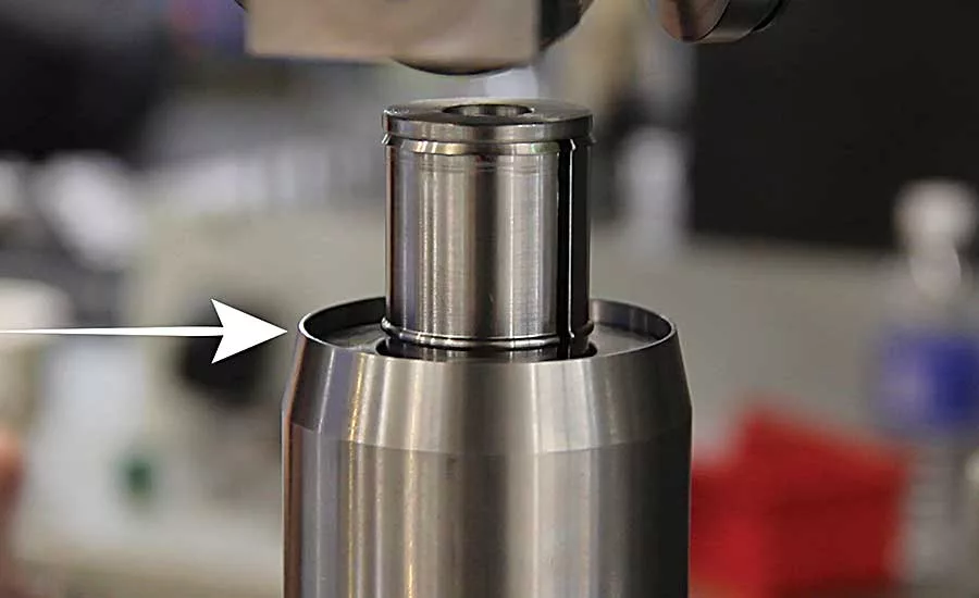
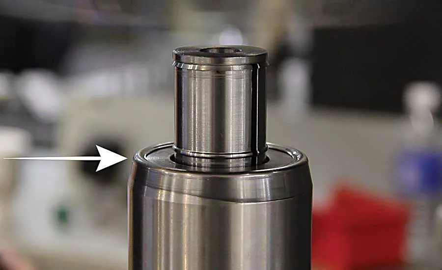
The articulating roller forming process is often used to prepare tube for insertion of a bearing. “You can use the process to create a groove on the outside of the part and a corresponding shoulder on the inside of the part, which serves as a hard stop for the bearing,” Wright explains. “Then, once the bearing has been inserted, you can form the end of the tube over to secure the bearing. In the past, a manufacturer would have had to machine a shoulder into the tube as a hard stop.”
When equipped with an additional set of vertically adjustable interior rollers, an articulated head can simultaneously form the outside and inside diameters of a workpiece.
Whether static or articulated, each roller and roller head assembly is custom-made to suit a specific application. However, roller heads are easily swapped out. Indeed, the same base machine can perform both orbital forming and roller forming. And, like orbital and radial forming, roller forming can be done as a standalone, semiautomatic process or integrated into a fully automatic assembly system.
Made from hardened tool steel, the rollers are typically 1 to 1.5 inches in diameter, says Lauritzen. The number of rollers on the head depends on the thickness and material of the part and how much force will be applied. Three rollers are most commonly used. Only two rollers might be necessary for a small part, while a very large part may require six.
“It’s application-specific, based on the size and diameter of the part, as well as how aggressively you want to move the material,” says Wright.
Roller forming can be done with a pneumatic, hydropneumatic or electric system.
“Ninety-five percent of applications are pneumatic,” says Wright. “If you need high precision or clean room operation, then you need an electric system.”
In some cases, a pressure pad can be built into the system to apply a preload to the assembly prior to forming. In some cases, a linear variable differential transformer can be built into the pressure pad to measure the stack height of the assembly before assembly as a quality check.
The key variables of the process are axial force, radial force (in the case of articulated roller forming), torque, rotational speed, time and displacement. These settings will vary depending on part size, material, and joint strength requirements. As with pressing, orbital forming and radial forming operations, roller forming systems can be equipped to measure force and displacement over time.
Equipment suppliers can provide guidance on the optimal parameters, as well as design guidelines for the preformed geometry of the parts. The goal is to have material follow the path of least resistance. Material shouldn’t move any farther than necessary to secure the joint.
Myriad Applications
Roller forming has been used on myriad assemblies in a variety of industries.
In the automotive industry, the method is used to assemble solenoids, sensor housings, cam followers, ball joints, shock mounts, filters, oil pumps, water pumps, vacuum pumps, hydraulic valves, tie-rods, air bag components, steering columns and manifolds for antilock brake systems.
“We recently did an application in which we formed a chrome cap over a threaded insert to assemble high-end lug nuts,” says Lauritzen.
One automotive supplier uses roller forming to secure a bearing inside the cast aluminum housing for a water pump. The company had been using a snap ring to secure the bearing. Roller forming produced a stronger joint and saved the cost of the ring and the time and expense of machining a groove for it.
In the medical device industry, roller forming is used to make joint replacements and catheter tips. In the electrical industry, roller forming assembles meters, outlets, capacitors and batteries. Aerospace assemblers use roller forming to produce bearings and poppet valves. The technique has even been used to make stands for camp stoves, breakers for table saws, and push-to-connect pipe fittings for plumbing.
Looking for a reprint of this article?
From high-res PDFs to custom plaques, order your copy today!


