New Technologies for 3D Vision
A wide range of 3D vision systems optimizes robot accuracy when performing random bin picking, error-proofing assemblies or dispensing adhesives.
A gentle nudge is often a more effective way to bring out the best in a worker than a firm push. Two common scenarios where this approach applies are just-hired workers and veteran ones that need to learn a new task.
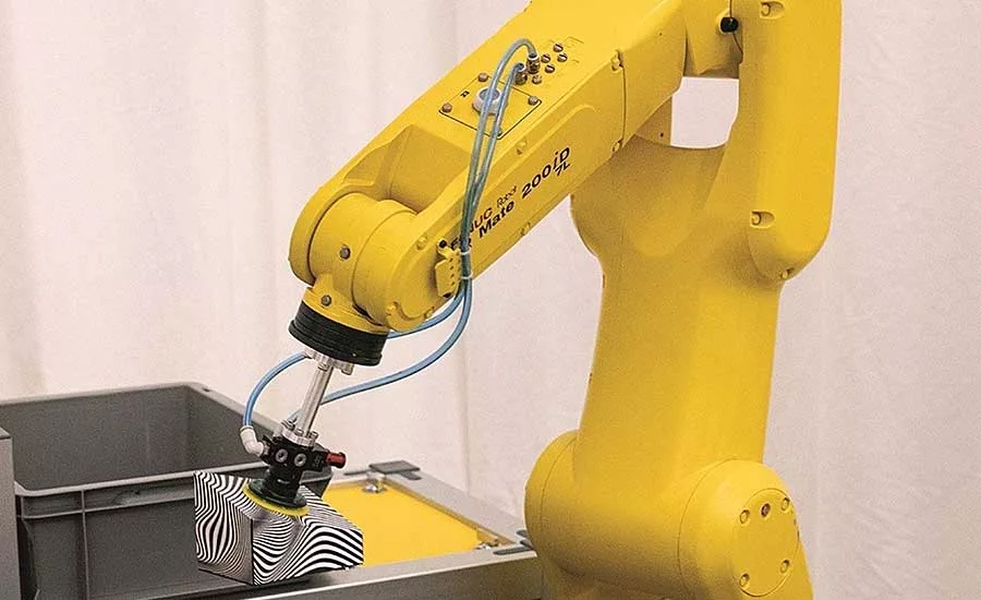
Such nudging can also be a good way to get the most out of a production line, especially when it involves new technology. Consider the example of 3D vision guidance for robots. Although first developed in the 1990s, the technology has been slowly implemented on the assembly line by manufacturers. Today, it’s a viable alternative to 2D vision for various tasks like random bin picking and dispensing adhesives.
“For about 30 years, we’ve helped manufacturers implement 3D vision guidance for their robots in lots of applications,” notes Bernhard Walker, 3D vision product manager at FANUC America Corp. “At first, it happened occasionally and involved the use of multiple 2D sensors to obtain roll, pitch and yaw data in the X, Y and Z axes. But now, it’s quite common, as the technology has evolved to the point where a single 3D camera or sensor—by which I mean its whole hardware package—can more quickly and accurately obtain this data.”
In 2012, FANUC introduced its 3DA series of 3D area sensors, which use structured light projection to create 3D maps of their surroundings and find parts in bins. After evaluating and deciding which part to pick, the controller accounts for the required reaching distance and collision avoidance before choosing the fastest picking option. If the controller decides a pick is unsuccessful or a part queue does not contain a part to pick, another image is taken and the process starts again using the new results.
Walker says that one automotive OEM is currently using the 3DA-1300 sensor on 10 production lines that fabricate camshafts. The company started with one sensor on one line several years ago. Each shaft weighs 5 to 10 pounds. Before using the sensors, the workshafts were lifted by a six-axis robot from racks. The downsides of this process, according to Walker, were the constant need to maintain the racks, and the related issues from out-of-spec racks, resulting in an uptime rate of only 60 to70 percent.
“The company has saved more than $1 million in maintenance over the years by eliminating the racks,” says Walker. “Now, the sensor enables the robot to take parts from a bin that holds 3,000 shafts vs. the old one that only held 100 shafts. Most importantly, uptime is consistently in the 97 to 98 percent range.”
Accurately grabbing parts from piles remains a big challenge for 2D machine vision systems. In contrast, 3D vision provides spatial geometric information in varying environments to help robots overcome this challenge. Such an assurance helps manufacturers optimize production.
Looking for quick answers on assembly and manufacturing topics? Try Ask ASM, our new smart AI search tool. Ask ASM
A Better Part Picker Upper
Like many technologies, 3D vision has variations. It can be passive or active. And, it can use time-of-flight (TOF), stereo camera or structured light imaging techniques.
A stereo-camera-based system that uses ambient light is considered to be passive, while a system that relies on structured laser lighting is an active one. In either case, the 3D imaging system must generate a point cloud, which is a set of data points in space that represents the external surface of the object.
“Over the last eight years or so, point cloud generation has been an increasing trend in 3D vision,” notes Walker. “Having this point cloud is important regardless of the imaging technique.”
A TOF camera works by illuminating the scene with a modulated light source, and observing the reflected light. The phase shift between the illumination and the reflection is measured and translated to distance. The light source can be a solid-state laser or an LED operating in the near-infrared range.
Walker says the TOF technique composes a 3D image the most quickly. However, a stereo camera or structured lighting system is typically more accurate than a TOF one.
“A 2D vision system is still great for capturing any object in the X and Y axis,” says Grant Zahorsky, a 3D machine vision engineer at Canon USA. “The problem is it doesn’t provide enough information regarding a part’s position or orientation in the 3D space of the Z axis. That is why 3D vision is so much better for picking parts from a pile or randomly picking them from a bin or tote.”
There are three types of bin picking, according to Zahorsky. Each type involves an increasing level of complexity, cycle time and cost.
Structured picking refers to positioning or stacking parts in an organized, predictable pattern so they can be easily imaged and picked. Semi-structured picking involves parts that are positioned in the bin with some organization and predictability to help aid imaging and picking. In random picking, the parts in a bin may have different orientations, overlap and even be entangled, further complicating the imaging and picking functions.
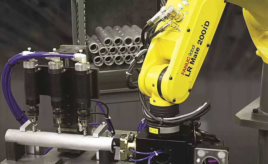
The iRVision 3DV series from FANUC is designed to effectively perform all types of bin picking. Model 3DV-400 came out in 2018, followed by the 3DV-600 and 3DV-1600 in the last two years. All of the systems can be robot-mounted or fixed, and used with any of the company’s robot controllers and four-axis, six-axis, collaborative, SCARA and delta robots. Optional iRPickTool software helps the robot detect randomly placed parts on a moving conveyor.
“The process begins with the system’s dual cameras taking a single-shot 3D image within 100 to 300 milliseconds,” explains Walker. “Each camera uses pseudo random points, or point texture projection, to create a 3D point cloud of the field of view. Depending on model, the field of view ranges from 400 to 1,600 millimeters cubed.
“After this, several software tools extract information out of the cloud to see the various types of 3D parts that the robot has to pick. This information ranges from pattern matching and part peak location, to blob and surface analysis. Once analysis is finished, all data is sent to the controller to tell the robot which specific part to pick.”
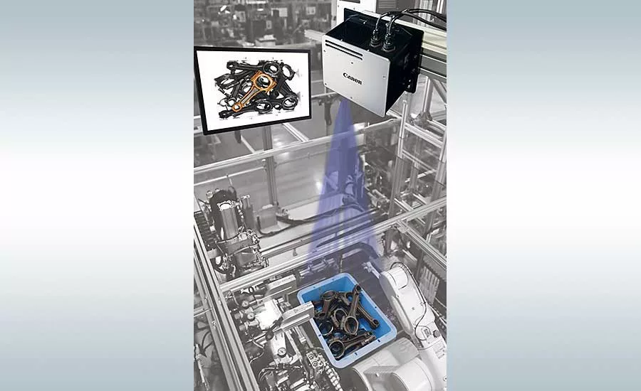
Canon offers a 3D vision system, the RV Series, which uses structured light projection and 3D scanning to produce point cloud data of external surfaces. Customers include integrators and automotive, medical-device and electronics manufacturers, as well as those that handle large amounts of small or heavy metal parts.
“Within one second, the system’s high dynamic range camera takes several images of the parts and averages them into one clear image,” notes Zahorsky. “This includes applying stripes and binary patterns to the parts, and performing software analysis to create a 3D point cloud.”
The next step is called quick discovery, where the vision system generates a model, based on the part’s physical properties, to make an initial guess of where each part is located in the bin. Then, a CAD model is precisely fit to the 3D point cloud, while simultaneously being fit to the 2D image.
“Grasp priority is then made by the software to determine the best way for the robot to pick up a part,” says Zahorsky. “This step takes into account how the gripper will interact with the part, as well as the best path for the robot to take to avoid colliding with other parts upon retrieval. Finally, the coordinates of the part to be picked up are sent to the robot for retrieval."
Dispensing and Error-Proofing
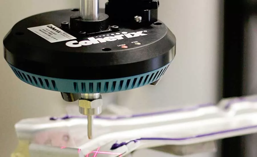
Two other common uses of 3D vision for robot guidance are dispensing and error-proofing. Coherix Inc. makes separate systems for each type of application.
The Predator3D instantaneously inspects and ensures that an adhesive, sealant or thermal-paste bead is correctly applied inline. Common applications are automotive glass windshields, quarter panels, and body, powertrain and battery assemblies. By using this technology, automotive manufacturers can overcome bead inspection challenges such as a high-profile triangular urethane bead (sometimes with molding next to it), and the reliability of high-contrast-based 2D cameras.
The system mounts around the dispensing nozzle, either on a robot arm or a pedestal setup, and communicates with most dispenser protocols. It features four high-speed 3D sensors that provide a 360-degree view of the bead up to 1,000 times per second. Proprietary algorithms in the system software quicken setup and increase inspection accuracy. The software also provides real-time, accurate measurements of bead width, height, volume and location, thereby helping manufacturers better control and optimize all dispensing processes.
“One automotive OEM has been benefitting from the Predator3D at its engine facility for the past two years,” notes Dr. Zhenhua Huang, general manager of Coherix Inc. Americas. “The system replaced two hi-res 2D cameras that were meant to ensure proper application of a sealant bead on each engine. However, the high production rate of 1,000 engines per day often resulted in a 16 percent false reject (false positive) rate of improper bead application coming from the cameras. With our system, the false reject rate is reduced to less than 0.3 percent, and the company is saving nearly $55,000 per day due to less labor and increased throughput.”
Tru3D sensors in the Robust3D system perform reliable error-proofing in a wide range of electronics and automotive applications. The latter include piston, rolling finger follower and valve assembly, and end-of-line inspection.
After capturing millions of data points to generate a 3D “as built” model of a part assembly, the system’s i-Cite software applies various inspection criteria to prevent critical failure downstream in the assembly process. Another benefit is full 3D part data traceability.
Looking for a reprint of this article?
From high-res PDFs to custom plaques, order your copy today!


.webp?height=200&t=1733742897&width=200 "Assembly News Now, episode 12: New Technologies for Robotic Screwdriving")

