Space Shuttle Gets a Helping Hand
Force sensor helps astronauts perform critical inspection task.

After the space shuttle Columbia exploded during re-entry on Feb. 1, 2003, NASA’s prime directive was to develop a way to inspect the spacecraft’s thermal protection system while in orbit. The space agency wanted to get detailed views of previously inaccessible areas on the outer surface of the orbiter. It also wanted astronauts to be able to reach these areas to make repairs.
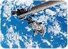
NASA met this goal by adding a 40-foot extension boom to the shuttle’s existing 40-foot robotic arm. The extra reach enables astronauts to view the leading edges of the wings and the underbelly of the shuttle in detail from inside the craft while in orbit. Besides video cameras, the end of the boom includes a platform to hold a crewmember in case repairs are needed.
NASA engineers were confident the boom could inspect the entire outer surface of the shuttle. But, could it safely and effectively support an astronaut making repairs? There was only one way to find out. When the space shuttle Discovery lifted off from Kennedy Space Center on July 4, 2006, it was outfitted with the new boom, and astronauts Michael E. Fossum and Piers J. Sellers were assigned the task of using it while simulating repairs.
To get an idea of the forces exerted on the boom by the astronauts and their tools during repairs in zero gravity, NASA engineers equipped the platform with a special load measurement device called an instrumented worksite interface (IWIF). The instrument was placed between the boom and an articulating foot restraint, which secures the astronaut during a space walk.
The main requirements for the load cell were size, range and resolution, says Greg Vaselakos, project engineer at Oceaneering. “JR3 had a small load cell that fit the range needed in the project, and even though the company hadn’t [supplied] aerospace hardware before, it was willing to work with us on the changes…we required,” Vaselakos says.
The load cell was positioned below the astronaut’s feet. The intent was not to measure the force that the astronaut was applying with his hands against the surface of the shuttle, but to measure the force that was being applied to the structure of the articulating foot restraint and boom after the astronaut’s body dampened the applied load.
Curt Carlton, senior engineer at Boeing, came up with the concept of putting the load cell at the base of the foot restraint. The foot restraint is a boot plate similar to the bindings on a pair of skis. It has a probe that plugs into sockets located on the space shuttle and the International Space Station. Both the sockets and the restraint are standard designs. The team built an adapter, with the load cell in the middle, that fits into the socket on the end of the boom. The adapter has another socket that the foot restraint plugs into.
“The whole IWIF assembly is very small because the crew member has to carry the device out onto the platform and install it. To uniformly distribute the load, most load cells have a tendency to be large, flat plates. We needed something compact,” Carlton says.
“Our multiaxis load cells are relatively small and measure [force in] six degrees of freedom,” says John Ramming, president of JR3. “[In] a Cartesian coordinate system, it will measure the force applied to [the X, Y and Z] axes, and then measure the torque applied to each of those three axes, translating into all six degrees of freedom.”
The original JR3 load cell that NASA selected was 5 inches in diameter and approximately 1 inch thick. “As we got into the actual design and capability of the load cell, it got a little bit larger,” Vaselakos says. “The final design was about 7 inches in diameter and 1.5 inches thick.”
JR3’s standard load cells are made out of aluminum. However, the company could also make them out of titanium. “That was very interesting to us because the strength of titanium allowed us to increase our margin of safety. Titanium is significantly stronger than aluminum,” Vaselakos says.
Titanium also had good material properties for measuring strain. It “gives” and returns to its original state. The IWIF needed a flexible structure that returned to its original configuration after a load was applied.
The final load cell has 32 strain gauges and six dual-access accelerometers. “The accelerometers helped us understand motion. We could correlate the load put into it to how much it made the load cell move,” Vaselakos explains.
The data recorders on the IWIF are battery powered. The batteries in the data recorder also energize the accelerometers and the strain gauges in the load cell. The system is controlled from a laptop computer on the aft flight deck of the orbiter. Commands and data are sent to and from the recorder via radio frequency communication.
Because the load cell is directly under the feet of the astronaut, it is a structural load path and has to meet a rigid list of requirements. Everything designed for use in space must meet high safety margins. The rule is always to overdesign for safety so there’s no way an astronaut can be injured, says Carlton.
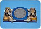
The final result isn’t glamorous. It looks like a long shoebox with instrumentation wrapped in what’s called a multilayered insulation blanket, but it did an excellent job.
The Neutral Buoyancy Lab is 100 feet wide, 200 feet long and 40 feet deep. Underneath the water are replicas of the space station, the payload bay of the shuttle, and the shuttle’s robotic arm.
A concern was that if an astronaut expended too much force while on the end of the 80-foot boom, it would impart very high loads on the joints in the arm, causing what is known as a “brake slip.” This effect would push the astronaut away from the shuttle. NASA’s analysis team estimated that there should not be more than 10 pounds of force put on the arm while performing repairs on the end of the boom.
“When you think about it, 10 pounds of force is very little,” Carlton says. “With the data from the IWIF, we plan to be able to modify power tools and the motions needed to do repair tasks. Many of these tasks are similar to filling cracks in Sheetrock. A trowel-type tool is used to smooth out a special filler we’ve specifically designed for in-orbit repairs. Another operation for carbon composite repair is very similar. [The astronauts use] a ceramic polymer adhesive that comes out of a caulk gun. It adheres to the surface as soon as it’s laid in place.
“We believe our analysis was conservative, and that the arm is more than robust enough to handle the approximately 10 pounds of force that would cause the brakes to slip.”
Still, every person is different. Even the same person using the same motion at different times can apply force differently, and that was virtually impossible for NASA engineers to analyze. Data from running the IWIF in orbit would be the only way to be sure. The data would also help train the astronauts for space walks, and it would help engineers design tools for zero-gravity repair work. For example, the tools might need to be more flexible, or they might need some type of load-alleviation device.
The IWIF met all expectations. The data it gathered is now being processed at Oceaneering Space Systems. The July flight proved that the IWIF can be used successfully to inspect and repair the outer surface of the shuttle.
After the space shuttle Columbia exploded during re-entry on Feb. 1, 2003, NASA’s prime directive was to develop a way to inspect the spacecraft’s thermal protection system while in orbit. The space agency wanted to get detailed views of previously inaccessible areas on the outer surface of the orbiter. It also wanted astronauts to be able to reach these areas to make repairs.
NASA met this goal by adding a 40-foot extension boom to the shuttle’s existing 40-foot robotic arm. The extra reach enables astronauts to view the leading edges of the wings and the underbelly of the shuttle in detail from inside the craft while in orbit. Besides video cameras, the end of the boom includes a platform to hold a crewmember in case repairs are needed.
NASA engineers were confident the boom could inspect the entire outer surface of the shuttle. But, could it safely and effectively support an astronaut making repairs? There was only one way to find out. When the space shuttle Discovery lifted off from Kennedy Space Center on July 4, 2006, it was outfitted with the new boom, and astronauts Michael E. Fossum and Piers J. Sellers were assigned the task of using it while simulating repairs.
To get an idea of the forces exerted on the boom by the astronauts and their tools during repairs in zero gravity, NASA engineers equipped the platform with a special load measurement device called an instrumented worksite interface (IWIF). The instrument was placed between the boom and an articulating foot restraint, which secures the astronaut during a space walk.
Designing the IWIF
The IWIF was jointly developed by Hamilton-Sundstrand Corp. (Windsor Locks, CT), the Boeing Co. (Chicago), and Oceaneering International Inc. (Houston). Sensor manufacturer JR3 Inc. (Woodland, CA) supplied the load cell for the instrument. The load cell was a custom version of one of JR3’s off-the-shelf products, a sensor that is normally used with robots on assembly lines. Mounted between the arm and the end-effector, the load cell gives the robot a sense of touch when manipulating tools and parts.The main requirements for the load cell were size, range and resolution, says Greg Vaselakos, project engineer at Oceaneering. “JR3 had a small load cell that fit the range needed in the project, and even though the company hadn’t [supplied] aerospace hardware before, it was willing to work with us on the changes…we required,” Vaselakos says.
The load cell was positioned below the astronaut’s feet. The intent was not to measure the force that the astronaut was applying with his hands against the surface of the shuttle, but to measure the force that was being applied to the structure of the articulating foot restraint and boom after the astronaut’s body dampened the applied load.
Curt Carlton, senior engineer at Boeing, came up with the concept of putting the load cell at the base of the foot restraint. The foot restraint is a boot plate similar to the bindings on a pair of skis. It has a probe that plugs into sockets located on the space shuttle and the International Space Station. Both the sockets and the restraint are standard designs. The team built an adapter, with the load cell in the middle, that fits into the socket on the end of the boom. The adapter has another socket that the foot restraint plugs into.
“The whole IWIF assembly is very small because the crew member has to carry the device out onto the platform and install it. To uniformly distribute the load, most load cells have a tendency to be large, flat plates. We needed something compact,” Carlton says.
“Our multiaxis load cells are relatively small and measure [force in] six degrees of freedom,” says John Ramming, president of JR3. “[In] a Cartesian coordinate system, it will measure the force applied to [the X, Y and Z] axes, and then measure the torque applied to each of those three axes, translating into all six degrees of freedom.”
The original JR3 load cell that NASA selected was 5 inches in diameter and approximately 1 inch thick. “As we got into the actual design and capability of the load cell, it got a little bit larger,” Vaselakos says. “The final design was about 7 inches in diameter and 1.5 inches thick.”
JR3’s standard load cells are made out of aluminum. However, the company could also make them out of titanium. “That was very interesting to us because the strength of titanium allowed us to increase our margin of safety. Titanium is significantly stronger than aluminum,” Vaselakos says.
Titanium also had good material properties for measuring strain. It “gives” and returns to its original state. The IWIF needed a flexible structure that returned to its original configuration after a load was applied.
The final load cell has 32 strain gauges and six dual-access accelerometers. “The accelerometers helped us understand motion. We could correlate the load put into it to how much it made the load cell move,” Vaselakos explains.
The data recorders on the IWIF are battery powered. The batteries in the data recorder also energize the accelerometers and the strain gauges in the load cell. The system is controlled from a laptop computer on the aft flight deck of the orbiter. Commands and data are sent to and from the recorder via radio frequency communication.
Because the load cell is directly under the feet of the astronaut, it is a structural load path and has to meet a rigid list of requirements. Everything designed for use in space must meet high safety margins. The rule is always to overdesign for safety so there’s no way an astronaut can be injured, says Carlton.
The final result isn’t glamorous. It looks like a long shoebox with instrumentation wrapped in what’s called a multilayered insulation blanket, but it did an excellent job.
Simulated Zero Gravity
The shuttle’s arm has many years of testing behind it, but the load cell had to be stress-tested to ensure it would continue to record data as expected in space. The IWIF was tested in NASA’s Neutral Buoyancy Laboratory, a 6.2 million-gallon swimming pool used to simulate zero-gravity conditions. The lab is also where astronauts were trained in how to use the new instrument.The Neutral Buoyancy Lab is 100 feet wide, 200 feet long and 40 feet deep. Underneath the water are replicas of the space station, the payload bay of the shuttle, and the shuttle’s robotic arm.
A concern was that if an astronaut expended too much force while on the end of the 80-foot boom, it would impart very high loads on the joints in the arm, causing what is known as a “brake slip.” This effect would push the astronaut away from the shuttle. NASA’s analysis team estimated that there should not be more than 10 pounds of force put on the arm while performing repairs on the end of the boom.
“When you think about it, 10 pounds of force is very little,” Carlton says. “With the data from the IWIF, we plan to be able to modify power tools and the motions needed to do repair tasks. Many of these tasks are similar to filling cracks in Sheetrock. A trowel-type tool is used to smooth out a special filler we’ve specifically designed for in-orbit repairs. Another operation for carbon composite repair is very similar. [The astronauts use] a ceramic polymer adhesive that comes out of a caulk gun. It adheres to the surface as soon as it’s laid in place.
“We believe our analysis was conservative, and that the arm is more than robust enough to handle the approximately 10 pounds of force that would cause the brakes to slip.”
Still, every person is different. Even the same person using the same motion at different times can apply force differently, and that was virtually impossible for NASA engineers to analyze. Data from running the IWIF in orbit would be the only way to be sure. The data would also help train the astronauts for space walks, and it would help engineers design tools for zero-gravity repair work. For example, the tools might need to be more flexible, or they might need some type of load-alleviation device.
Mission Accomplished
During the July 2006 shuttle flight, astronauts were secured to the articulating foot restraint, which was plugged into the instrumentation package, and then into the tip of the 80-foot boom. While the astronauts simulated repair movements, the instrumentation measured forces, movements and accelerations applied to the end of the extension. The main goal was to determine the maximum force that could be applied to the arm while maintaining a stable arm position. Even a simple movement in the weightlessness of outer space could cause reactions far different than predicted in the best lab environment.The IWIF met all expectations. The data it gathered is now being processed at Oceaneering Space Systems. The July flight proved that the IWIF can be used successfully to inspect and repair the outer surface of the shuttle.
Looking for a reprint of this article?
From high-res PDFs to custom plaques, order your copy today!


