Automation Profiles: Automation Ensures Driver Safety
Grammer AG of Amberg, Germany, assembles active headrests on a 14-station automated assembly system designed by DEPRAG.
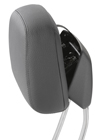
 Today, active headrests form part of every vehicle’s passive safety system. In the event of a collision, the headrests automatically tilt forward to support the head for a few valuable milliseconds, preventing whiplash and spinal cord injury.
Grammer AG of Amberg, Germany, assembles active headrests, seats and other interior components for manufacturers of cars, trucks, buses and trains. Grammer produces the headrests on a 14-station automated assembly system designed by DEPRAG. The system is 8.34 meters long, 2.55 meters wide and 2.4 meters high, excluding the parts feeding equipment. The cycle time is less than 10 seconds, resulting in a production rate of more than 360 headrests per hour.
Grammer’s active head rest consists of three major components: a release unit, a carrier and a slide. At the first station, operators manually position these core components onto a precision locating pallet along with two guide springs.
Station 2 is an automatic inspection cell to insure that all the components are present and correctly positioned on the pallet.
Station 3 is an inspection and assembly station. The release unit is examined by sensors. Is the label present? Are the manually positioned centering devices correctly configured? If so, the release unit is automatically positioned onto the carrier and snapped into place.
At station 4, two guide tubes per assembly are separated, aligned and placed in position on the carrier using a linear-track feeding system. Also, two grooved pins are shot into place from a vibratory bowl feeder with a blow feed separator. The pins are then automatically pressed into the carrier to secure the guide tubes.
At station 5, a lock-pin is supplied by a vibratory bowl feeder and automatically inserted into the slide. At station 6, the interior of the release-carrier subassembly receives the two guide springs, which were manually placed onto the pallet at the first station. Automatic grippers pick and place the springs.
Station 7 confirms the quality of the work from station 6. In addition, a vacuum gripper automatically places a pair of washers over the guide tubes.
At station 8, two coil springs are simultaneously set in place over the guide tubes and washers, using an automated dual gripper. Stations 9 and 10 are presently open positions to accommodate future expansion or additional processes.
At station 11, the slide is automatically located and locked onto the release-carrier subassembly. This slide unit causes the headrest to move toward the head of the driver at lightning speed during an accident.
At station 12, a simulated emergency test is performed. The release unit is activated, and the slide module is triggered so the function of the finished headrest can be checked. The statistics received from this test, including date, time and the operator’s employee number, are saved to a computer, where they can be processed in Excel and printed out.
At Station 13, the completed module receives a label with the test results generated at the previous station. At the final station, assemblies that have passed the functionality test are removed from the pallet and packaged by the operator. Faulty assemblies are sent to a rework station by the system’s conveyor. There, a display panel indicates the specific assembly or test failure, so an operator can fix the problem.
For more information, call 800-4-DEPRAG or visit www.depragusa.com.
Editor’s note: Whether you’re a systems integrator or the in-house automation team of an OEM, if you’ve designed a system that you’re particularly proud of, tell us about it. Send an e-mail to John Sprovieri, editor of ASSEMBLY, at sprovierij@bnpmedia.com, or call 630-694-4012.
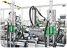
This 14-station automated assembly system produces one headrest every 10 seconds. Photo courtesy DEPRAG
Grammer AG of Amberg, Germany, assembles active headrests, seats and other interior components for manufacturers of cars, trucks, buses and trains. Grammer produces the headrests on a 14-station automated assembly system designed by DEPRAG. The system is 8.34 meters long, 2.55 meters wide and 2.4 meters high, excluding the parts feeding equipment. The cycle time is less than 10 seconds, resulting in a production rate of more than 360 headrests per hour.
Grammer’s active head rest consists of three major components: a release unit, a carrier and a slide. At the first station, operators manually position these core components onto a precision locating pallet along with two guide springs.
Station 2 is an automatic inspection cell to insure that all the components are present and correctly positioned on the pallet.
Station 3 is an inspection and assembly station. The release unit is examined by sensors. Is the label present? Are the manually positioned centering devices correctly configured? If so, the release unit is automatically positioned onto the carrier and snapped into place.
At station 4, two guide tubes per assembly are separated, aligned and placed in position on the carrier using a linear-track feeding system. Also, two grooved pins are shot into place from a vibratory bowl feeder with a blow feed separator. The pins are then automatically pressed into the carrier to secure the guide tubes.
At station 5, a lock-pin is supplied by a vibratory bowl feeder and automatically inserted into the slide. At station 6, the interior of the release-carrier subassembly receives the two guide springs, which were manually placed onto the pallet at the first station. Automatic grippers pick and place the springs.
Station 7 confirms the quality of the work from station 6. In addition, a vacuum gripper automatically places a pair of washers over the guide tubes.
At station 8, two coil springs are simultaneously set in place over the guide tubes and washers, using an automated dual gripper. Stations 9 and 10 are presently open positions to accommodate future expansion or additional processes.
At station 11, the slide is automatically located and locked onto the release-carrier subassembly. This slide unit causes the headrest to move toward the head of the driver at lightning speed during an accident.
At station 12, a simulated emergency test is performed. The release unit is activated, and the slide module is triggered so the function of the finished headrest can be checked. The statistics received from this test, including date, time and the operator’s employee number, are saved to a computer, where they can be processed in Excel and printed out.
At Station 13, the completed module receives a label with the test results generated at the previous station. At the final station, assemblies that have passed the functionality test are removed from the pallet and packaged by the operator. Faulty assemblies are sent to a rework station by the system’s conveyor. There, a display panel indicates the specific assembly or test failure, so an operator can fix the problem.
For more information, call 800-4-DEPRAG or visit www.depragusa.com.
Editor’s note: Whether you’re a systems integrator or the in-house automation team of an OEM, if you’ve designed a system that you’re particularly proud of, tell us about it. Send an e-mail to John Sprovieri, editor of ASSEMBLY, at sprovierij@bnpmedia.com, or call 630-694-4012.
Looking for a reprint of this article?
From high-res PDFs to custom plaques, order your copy today!


