TE’s New Terminal Design Reduces Insertion Force
Liteforce design helps address the conflict between technological requirements and assembly ergonomics
Automotive innovation is driven by environmental, safety and lifestyle requirements. This means manufacturers are putting more electronic content in their vehicles with ever-increasing numbers of electronic control units (ECUs).
Modern automotive ECUs can require more than 300 electrical connections. Populating these connectors manually requires a good deal of force and physical effort from assembly line workers. Over time, this could lead to repetitive strain injury and loss of working time. Manufacturers need to ensure that this physical effort does exceed what is permissible by local labor unions.
To reduce the physical effort of assemblers, engineers can group multiple wires into a single connection. In other words, inserting five six-wire connectors is better than inserting 30 individual wires. Yet, each module may still require a mechanical mating-assist feature, such as a lever. Also, the mounting position of connector interfaces in a vehicle is often difficult to reach and can pose a challenge to assemblers.
The challenge is how to facilitate high-pin-count connectivity without placing excessive physical strain on workers and without compromising the mechanical or electrical performance of the interconnection.
Hertzian-Style Contacts
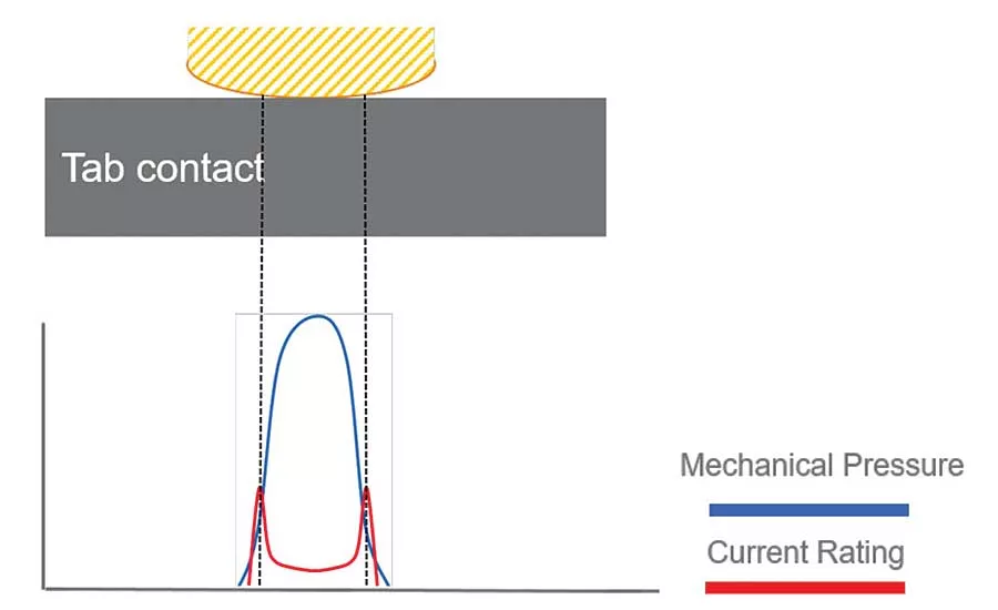
Traditionally, the electrical and mechanical contact between the mating partners, such as the receptacle terminal and tab, is established by a spherical shape pressed against a flat, rectangular tab. This is known as the “Hertzian-style” contact and is the standard contact design for tin-plated receptacle contacts, mated with solid rectangular tabs.
To establish a reliable electrical interconnection, the sphere-against-flat contact design requires a comparatively high normal force, which permanently presses the spherical area against the flat tab surface. The force is exerted by the terminal’s spring beams.
The normal force is needed to break through the tin oxide layer that quickly forms on tin-plated surfaces. This local removal of tin oxides is necessary to bring the metal lattices of terminal and tab in direct contact. In addition, a high normal force is needed to ensure that the interconnection has a low electrical resistance and a high vibration resistance.
Looking for quick answers on assembly and manufacturing topics? Try Ask ASM, our new smart AI search tool. Ask ASM
Due to the high level of normal force, the areas of maximal load and the electrical interconnection, or current flow, do not coincide. The current rating reveals that the optimum area for current flow is a somewhat ring-shaped zone encircling the maximum load area. In this ring-shaped zone—the so-called “a-spots”—surface asperities establishing the real electrical contact area carry the maximum electrical load.
An understanding of the functional principle of the Hertzian-style contact shows that a simple reduction of the normal force will not work. If the force applied to the tab is insufficient, the tin oxide layer will not be removed, the electrical resistance will increase, and the vibration resistance will be reduced. A solution to the increased insertion forces associated with high-pin-count connectors cannot be achieved with Hertzian-style contact.
The Hertzian-style contact also brings another disadvantage when deployed in automotive applications. If the interconnection between terminal and tab is subject to relative movement or vibration, the mechanical interconnection will be maintained longer than the electrical interconnection.
Shear traction and stick-slip effects can move the sphere geometry sideways or back and forth. During this displacement movement, the a-spots in the narrow, ring-shaped current flow zone can break up along with the level of the lateral displacement, because the level of adhesion is lower in the peripheral zone.
In addition to increased mechanical wear, this will cause the electrical resistance to rise. In extreme cases, it can lead to a complete loss of the electrical connection.
The Hertzian-style contact has a number or limitations when it comes to resolving the issue of increased insertion forces and excessive physical strain for automotive applications requiring high pin-count connectors.
Wave-Form Receptacle
TE Connectivity has developed an innovative terminal design that combines a spring beam design with a wave-structure-based contact geometry that reconciles the paradox of lower insertion forces and durable high-pin-count connectors.
To reduce the normal force, two key technical requirements need to be fulfilled. First, the tin oxide layer on the corresponding contact areas needs to be broken-up. Second, the areas where the a-spots form need to be enlarged because the constriction resistance, limiting the current, depends on the total surface for the electrical connection.
To achieve the maximum current carrying capacity and vibration resistance, the right amount of pressure is required exactly where the a-spots are established.
The initial approach to a modified terminal beam design followed the principle of avoiding separation between the areas of maximum load and maximum current rating. The terminal selected for development was TE’s globally established, automotive-grade MQS.
The first step of modification was a contact geometry without a centered maximum load area. This experimental sphere-against-dimpled flat contact resulted in a higher current rating peak by ensuring the maximum load and current areas coincided.
Although this suggested that the underlying principle was viable, from a practical point of view it was clear it would be a challenge to ensure a precise match of the two contact partners during connector engagement in a manufacturing environment. The risk of a potential mismatch appeared particularly high in dense high-pin-count applications with minimum tolerances.
The second approach was a spherical contact with a circular wall shape and a dimple in the middle. By avoiding the maximum pressure zone in the middle of the sphere, maximum load and maximum current rating again coincided. The rim of the circular wall also proved an efficient way of breaking open the tin oxide layer.
During this phase of development, the first of the two technical requirements had been achieved. Allowing for a potential axial or radial misalignment between terminal beam and tab, an even pressure distribution between the circular rim of the dimpled sphere and the flat tab surface could not always be ensured. This meant that half the incremental benefit could potentially be lost due to an angled contact pressure.
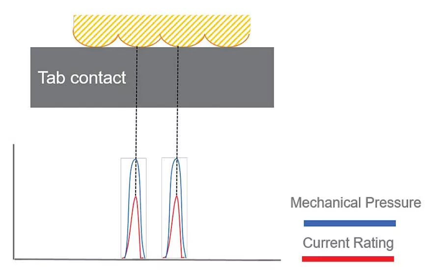
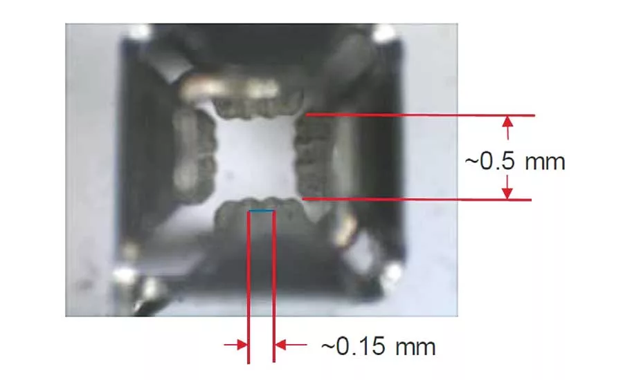
The solution was finally found in a sinusoidal wave structure. During the connector engagement, the wave rims break up the tin oxide layer and bring the tin metal lattices in direct contact. Since the areas of peak mechanical load and peak current rating coincide, a lower normal force is sufficient to establish the optimum electrical and mechanical interconnection.
This innovative wave structure proved a highly effective way of breaking up the tin oxide layer by depositing the oxides in the wave “troughs” where they do not cause disruption. In addition, the contact geometry features four waves, ensuring a sufficient number of maximum load and current areas and a-spots are formed, even in the case of axial misalignment between the terminal beams and the flat tab.
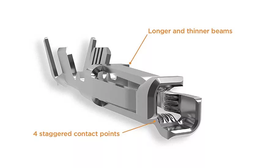
Provided at least two waves on each beam are in contact, the electrical and mechanical requirements are achieved. Finally, to reduce the normal force, the terminal spring beams were narrowed and extended and the points of contact staggered.
This new wave-structured contact geometry, combined with the new spring beams, comprises
TE’s innovative Liteforce terminal technology that reduces the insertion force required for high pin-count
connectors while at the same time increasing their current rating somewhat, or alternatively, increasing vibration resistance and current rating notably.
Electrical and Mechanical Performance
In tests, the Liteforce contact technology revealed several advantageous characteristics in comparison to standard sphere-against-flat contacts.
Two variants of the Liteforce terminal were tested: One designed for less normal force and one for standard normal force. The terminal designed for less normal force showed a reduction in insertion force of up to 52 percent and an increase in current carrying capacity of 16 percent. Vibration resistance remained the same. The terminal designed for standard normal force showed a reduction in insertion force of just
3 percent, but an increase in current carrying capacity of 22 percent. Vibration resistance increased by one class. For other terminals, such as AMP MCP, insertion force remained the same, current capacity increased by 25 percent, and vibration resistance improved by up to two classes.
The lower mating force can significantly reduce the physical strain on assemblers working with high pin-count connectors. Ultimately, this can lead to fewer workplace injuries and lost working time. It can also help automotive manufacturers remain compliant with labor regulations.
Depending on the pin count of the connector, the lower mating force can reduce the need for costly installations aids, such as levers. In addition, contact lubrication and its potential long-term effects can be avoided completely.
The four redundant contact areas ensure that the impact of axial misalignment between the terminal beams due to vibration is reduced. Furthermore, if the normal force is left unchanged, the wave structure technology can greatly increase the vibration resistance in comparison to a standard sphere-against-flat contact.
TE’s technology can meet and exceed the mechanical and electrical performance of standard Hertzian contacts. The wave structure contact geometry on the terminal beams was tested and verified on a modified MQS terminal. Other terminal deployments of the wave-form technology are already in the market and in series applications.
Liteforce contact technology can resolve the potentially conflicting goals of ensuring assembly line workers’ health and meeting technical performance requirements of connectors, as well as potentially reducing the complexity and cost of connectors by eliminating the need for additional mating assist features.
Looking for a reprint of this article?
From high-res PDFs to custom plaques, order your copy today!


