Automation University
Tips for Tooling Feeder Bowls
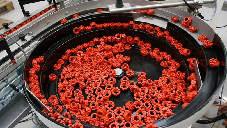
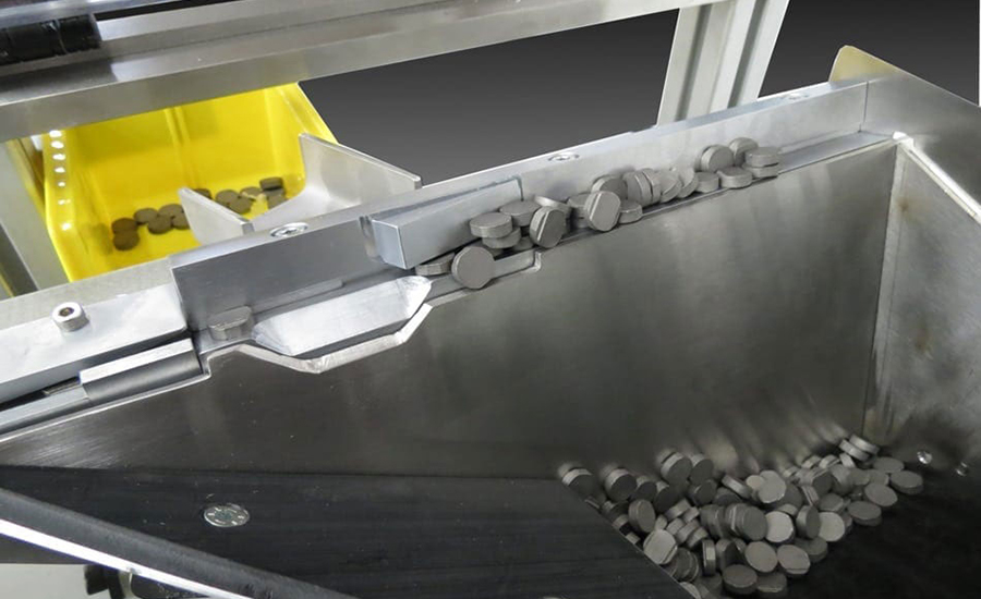
As a rule of thumb, assemblers should provide the feeder manufacturer with enough parts to run a bowl for 1 hour. Photo courtesy RNA Automation
A voodoo priest can foretell the future by tossing bones, sticks and other objects on the ground and interpreting their alignment.
An automation engineer can predict how parts will behave in a vibratory feeder bowl by dropping a handful on a table and analyzing their positions. Engineers can’t be sure what a part will do, especially under vibration, without knowing its center of gravity, and they can’t tell that from a drawing. One way to find that out is to drop the parts on a tabletop and look at their natural orientations.
Comparing a bowl builder to a voodoo priest is an apt metaphor. Tooling a vibratory feeder bowl is truly a black art. Indeed, two bowl makers working side-by-side on bowls for the same part may devise two completely different systems. Every bowl builder has favorite techniques for selecting parts. Creativity and experience are important.
Start With the Part
The first step in building a bowl is to analyze the geometry of the part. The builder needs to know all the potential positions the part might take in the bowl. The builder also looks for dimensional features that can be used to orient the part. If it’s hard to tell one end of the part from the other, it will be difficult to orient.
Engineers typically start with the required orientation of the part and work backwards. Can two or three parts be stacked together without interlocking? Is there a good surface for the parts to push against each other? If not, the parts will be difficult to feed.
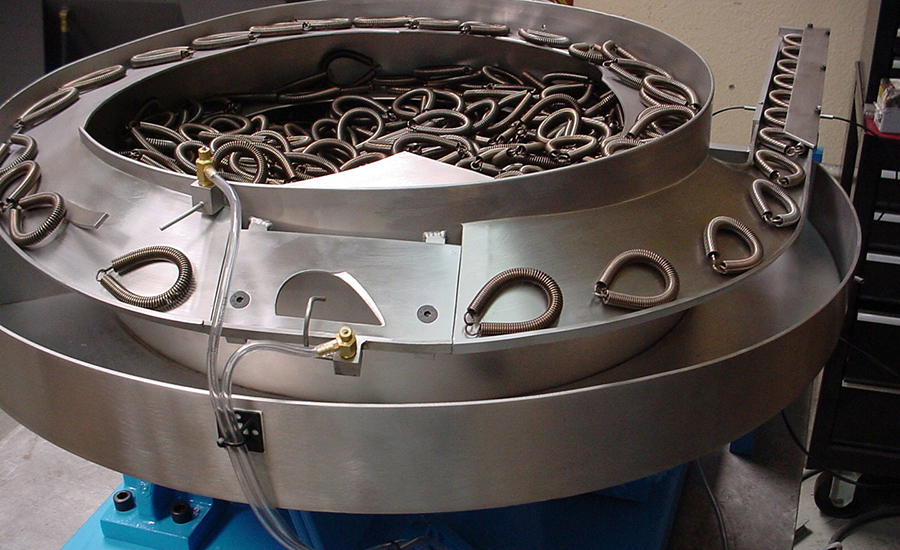
When designing parts feeders, engineers typically start with the required orientation of the part and work backwards. Photo courtesy West Coast Vibratory Feeders
Another early step is to put several parts in a generic bowl with a flat track to see how they react under vibration. The goal of this exercise is to discover the part’s natural orientation and to see how many parts accept that orientation. For example, a pen cap will likely feed with the open end trailing, because more weight is at the closed end.
If 80 percent of the parts come up in a certain position—even if it’s the wrong position—engineers will start with that position and look for ways to change it. Engineers should not fight the part; that will only lead to a small percentage of parts to work with from the beginning.
Looking for quick answers on assembly and manufacturing topics? Try Ask ASM, our new smart AI search tool. Ask ASM
Once the builder has an idea of the features and behavior of the part, the tooling process can begin. Some parts of the bowl can be designed and simulated with CAD software; others by cutting them out of pattern paper and attaching them to the bowl with masking tape. Often, the bowl builder will tool the bowl in stages, installing and testing one section of track before constructing the next one.
The first section of track singulates the parts. Builders get the parts in a single line simply by narrowing the track. A cam or wiper gets them into a single layer. The goal is to be able to accept or reject the parts one at a time.
Subsequent sections of track are responsible for getting the part in the correct orientation. These sections have two tasks: to save parts that are slightly misaligned and to reject those that can’t be saved. To maximize the feed rate, bowl builders try to save as many parts as possible.
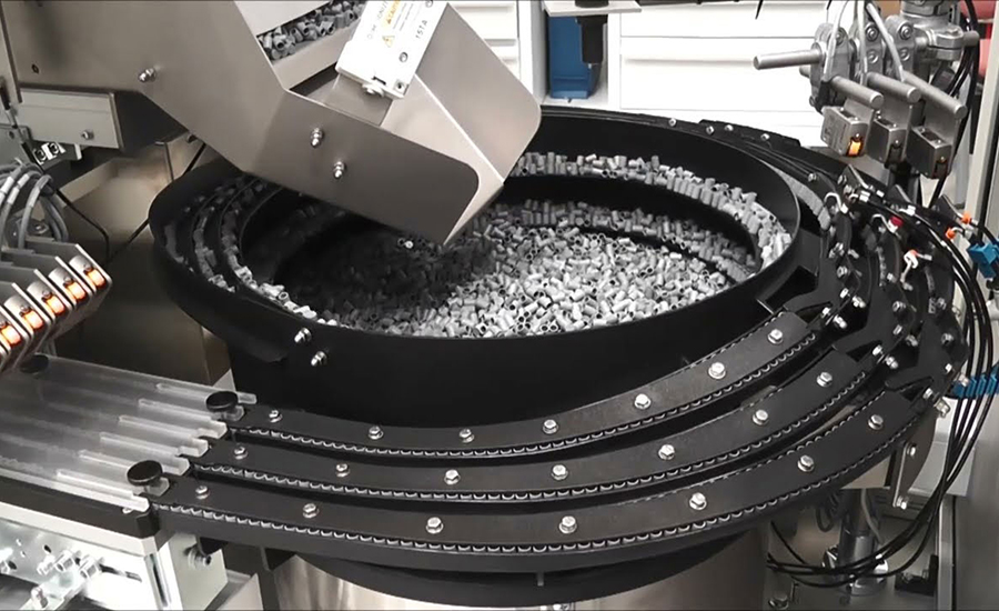
An early step in designing a feeder is to put several parts in a generic bowl with a flat track to see how they react under vibration. The goal is to discover the part’s natural orientation. Photo courtesy RNA Automation
Bowl builders have several options for orienting a part. A vertical step or a ramp can turn a part 90 degrees. A sweep or blade can rotate a part or catch and hold a protruding feature. The track itself can be shaped to fit a particular part contour, or the track can be angled to fan out the parts and take advantage of the part’s center of gravity.
Another option is to cut a gap into the wall or floor of the track. Correctly oriented parts will glide over the gap, but misoriented parts will fall through.
The last section of track contains the parts and feeds them to an in-line feeder or a pick-and-place device. Often, this section will contain one final screening device for misaligned parts. Then, the parts will be tightly confined by rails, or the section will be enclosed. Once the part is in the right orientation, engineers don’t want lose it.
Once the bowl builder gets the parts, it usually takes four to eight weeks to deliver the bowl. Actual build time might be as little as eight hours for a symmetrical, cylindrical part with a simple orientation, or as much as 300 hours for a multitrack bowl with interchangeable tooling that can feed more than part. An average bowl takes 40 hours to craft.
The Devil in the Details
Vibratory feeder bowls are usually made from 300 series stainless steel, because it’s durable and easier to weld than other stainless alloys. Standard bowls are made from 304 stainless, while bowls for food and medical applications are made of 316 stainless.
Various coatings can be applied to the bowl to protect fragile parts, reduce noise, improve part traction, and increase the durability of the bowl. Feeder bowls get smoothed down with use, so parts have less traction. A coating will increase the life of the bowl.
The size of the bowl depends on the size of the part, but a good starting point is what bowl builders call “the rule of seven.” Measure the largest dimension of the part, multiply that by seven, and that will provide a minimum diameter of the bowl.
Vibratory feeder bowls are usually made from 300 series stainless steel, because it’s durable and easier to weld than other stainless alloys. Photo courtesy Engineered Automation of Maine Inc.
From there, the size of the bowl can be modified depending on the feed rate and the space limitations of the assembly system. If the feed rate is high, the bowl will have to be enlarged to accommodate more parts and more lanes. Alternatively, the assembler can add a hopper feeder that replenishes the bowl whenever the level of parts reaches a minimum level.
The width of the track is also a function of part size. If the part is 2 inches wide, the track also has to be 2 inches wide. If the part is long and slender, the track may have to be wider.
The pitch of the track—how steeply it rises out of the bottom of the bowl—varies with the maximum height of the part. The bowl builder has to provide enough clearance so that two or three parts stacked on top of each other won’t jam between the tracks. A flat part can be fed in a low-profile, low-pitch bowl. If the part must stand on end or drop into a parallel track, the bowl will have to be made taller to accommodate that.
The key is not to get the climb rate too steep, because engineers will have to tune the bowl very high to push the parts up the slope. Engineers also have to think about what will happen when the parts come out of the bowl and start going downhill. If they go too fast, they will vibrate out of control.
Bowl Building Requirements
To design and build a vibratory feeder bowl, the supplier will need some help from the assembler. Part drawings, including dimensional tolerances, are useful.
Assemblers should also provide an honest estimate of the desired feed rate. The higher the feed rate, the more costly the bowl, so assemblers are well-advised to provide a realistic feed rate. As a safety factor, some manufacturers might be tempted to ask for a higher feed rate than they really need. Bear in mind, however, that bowl builders will always strive to exceed the requested rate, so those manufacturers are just needlessly increasing their costs.
The biggest need, of course, is the part itself. This may seem obvious, but it’s a frequent trouble spot in the bowl building process. A prototype part can be used to issue a quote on a bowl or determine its “feedability,” but production parts are mandatory for building the bowl. Similarly, bowl makers say it’s not uncommon for customers to change part suppliers while the bowl is being built. If these “new” parts differ only slightly from the parts used to design the bowl, the feeder might not work as expected.
A few parts are usually enough for a bowl builder to determine if the part can be fed and to provide a quote on the project. But, to build and test the bowl, the manufacturer will need a bulk supply of the parts. The amount of parts needed varies with the part size and feed rate, but bowl manufacturers have some rules of thumb. Most builders want at least enough parts to fill the bowl with two or three layers of parts.
Bowl builders will want to simulate the weight that will be in the bowl, especially with heavy parts, because as the bowl empties and the weight gets lighter, the bowl will vibrate harder. Engineers want to find the tuning range that works when the bowl is full as well as when it is almost empty.
Another rule of thumb is to provide enough parts to run a bowl for 1 hour. If the feed rate is 20 parts per minute, the builder need at least 1,200 parts.
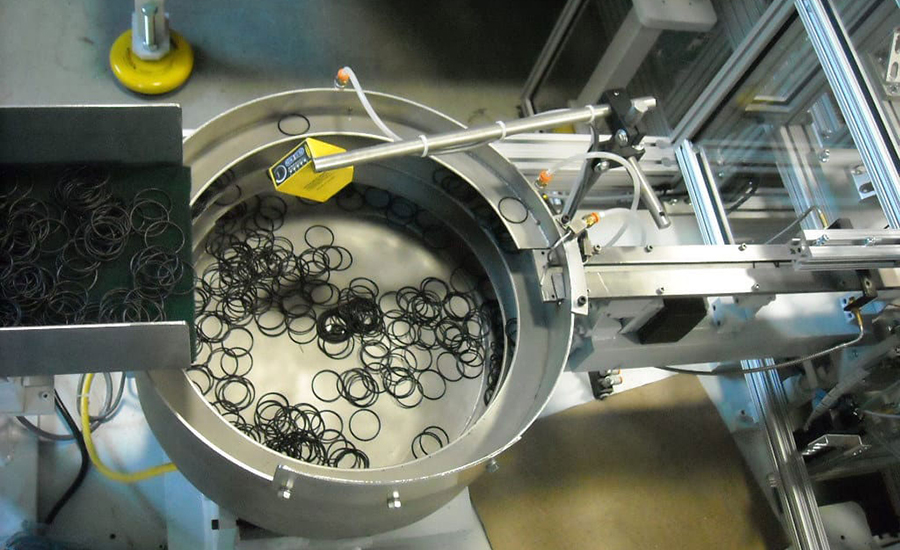
Assemblers are well-advised to contact their bowl suppliers early in the design process—as soon as they have a rough idea of how the part will be configured. Photo courtesy CDS Lipe Manufacturing
Bowl builders will need extra parts if the feeder will be working in conjunction with a supplementary hopper. In addition, if the parts are plastic, the bowl builder may need more samples than if the parts are metal. That’s because plastic deteriorates after a period of recirculating through a bowl during testing.
Assemblers can help bowl builders in other ways besides providing parts. For example, assemblers are well-advised to contact their bowl suppliers early in the design process—as soon as they have a rough idea of how the part will be configured. In many cases, bowl builders can suggest a design change—a small feature or a little bulk at one end of the part—to help the bowl singulate and orient the part. It may cost a few pennies more per part to add such a feature, but it could save thousands of dollars on the bowl and increase the feed rate.
Bowl builders also need to know the overall design of the line and even conditions on the shop floor. For example, they will need to know what sort of device or process the parts will exit into, so they can anticipate problems with back-pressure. It’s also good to know about sound level requirements or if there is airborne oil or water, which could affect the performance of the feeder.
Assemblers can also help by being flexible. For example, bowl builders may ask assemblers to adjust part tolerances or alter the part orientation to ensure optimal feeding. For example, a pin can’t be fed on its point, but it’s easy to feed lying down. Rather than ask for an impossible orientation, it’s better to find the most reliable position to feed the part and design the assembly machine from there.
Step Feeder Orients Automotive Magnets
Magnets are used in myriad automotive components. Aside from electric motors, magnets can be found in anti-lock braking systems, transmission and oil pan chip collectors, fuel pumps, air bag actuators, steering sensors, dashboard instruments, and stereo speakers. Magnets even play a role in the sensors used to detect low tire pressure.
Performance Feeders Inc. recently designed and built a step feeder system to supply two sizes of magnets for an automotive product. Engineers at Performance Feeders opted for a step feeder, rather than a vibratory bowl, for space savings and durability.
A step feeder consists of a baseplate with a hopper. On the back side of the hopper, a stepped feeding mechanism raises parts from the bottom of the hopper to the top. The steps are raised one at a time, creating a shelf that parts sit on. The width of each step matches the width of the parts.
As the steps move upwards, parts that are not seated fully on the shelf fall back into the hopper. When the step reaches the top, it deposits correctly oriented parts to a single-track linear feeder. Vibration is only used to convey parts in the linear feeder. Compared with vibratory bowl feeders, step feeders are much gentler on the parts.
This step feeder lifts magnets out of a hopper and deposits them to a vibratory track. Misoriented parts drop back into the hopper. Magnets that are the wrong size are ejected into a yellow bin. Photo courtesy Performance Feeders Inc.
In Performance Feeders’ system, magnets are lifted out of the hopper onto an orienting section of a vibratory track. Misoriented parts drop back into the hopper. Magnets that are the wrong size are ejected into a yellow bin.
Correctly oriented parts are transferred into the assembly line by a 60-inch long vibratory inline track made from hardened steel and driven by two- and three-spring drivers.
Proximity sensors monitor the parts level in the track. A sensor at the track entrance controls the step feeder, turning it on when parts are needed in the track. The sensor near the track exit issues an alarm if the supply of parts gets too low.
A belt-driven prefeeder, which stores 0.25 cubic feet of parts, keeps the step feeder supplied with parts. A photoelectric sensor on the step feeder monitors the parts level and turns on the prefeeder when parts are needed.
To see a video of the feeder in action, click here. For more information on parts feeding equipment, visit https://performancefeeders.com or visit the company’s booth at The ASSEMBLY Show South.
ASSEMBLY Online
For more information on parts feeding, read these articles:
Flex Feeder Accommodates Multiple Parts
Centrifugal Feeder Supplies Parts for Irrigation System
Vision System Helps Vibratory Feeder Bowl Orient Parts
Looking for a reprint of this article?
From high-res PDFs to custom plaques, order your copy today!


