Clinching High-Strength Steel Sheets
Photo: Akmad Bayuri / iStock / Getty Images Plus
Clinching is becoming increasingly popular for joining sheet metal in the automotive and aerospace sectors.
In clinching, a punch and die are used to plastically form a mechanical interlock between metal sheets. The technique produces a round, button-type connection between two to four layers of sheet metal. The process can join metal sheets of different thicknesses or materials, and it will not damage anticorrosive coatings on the metal. The minimum thickness for any one sheet in the assembly is 0.1 millimeter, and the entire stack can be up to 12 millimeters thick.
The tools consist of a punch and a die. The punch forces the layers of sheet metal into the die cavity. The pressure exerted by the press forces the punch-side metal to spread outwards within the die-side metal.
In the automotive industry, clinched joints are often used as an alternative to spot welding for body-in-white assemblies. However, clinched joints are not as strong as spot welds. As a result, researchers are seeking ways to increase the load-bearing capacity of clinched joints. For example, some studies have looked at heat-treating clinched joints, while others have looked at augmenting the joint with adhesive.
Our study examines a method for increasing the load-bearing capacity of clinched joints by locally modifying the microstructure of the joined materials—especially in the area of the neck of the joint—through resistance heating.
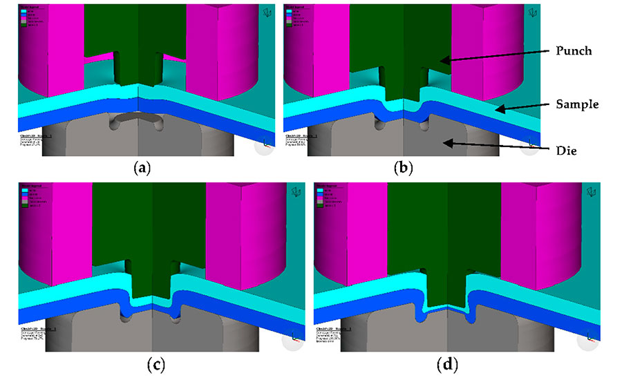
The typical steps of creating the clinched joint include clamping, pressing, bottom-forming, and interlock-forming. | Illustration courtesy Technical University of Košice
Materials and Methods
For our study, we chose two types of steel: HCT600X and HX420LAD. Both materials were 1.5 millimeters thick and galvanized on both sides.
HCT600X is a dual-phase steel with a multiphase structure consisting of hard martensite islands dispersed within a soft ferrite matrix. Dual-phase steel finds extensive application in the automotive sector. It is commonly employed in various structural components, such as automobile chassis, beams and guide rails. These parts experience intricate loads during practical usage, particularly in areas near geometric irregularities where stress tends to concentrate. Consequently, local plastic deformation may transpire when subjected to extreme loads.
Looking for quick answers on assembly and manufacturing topics? Try Ask ASM, our new smart AI search tool. Ask ASM
HX420LAD is a high-strength, low-alloy (HSLA) steel. HSLA steels have gained significant popularity due to their improved weldability and cost-effectiveness. HSLA steel offers several advantages, such as high specific strength and good low-temperature toughness. Compared to traditional steel, it enables reduced material consumption, enhanced reliability and decreased costs when manufacturing components with an equivalent load-bearing capacity. The combination of micro-alloying and controlled rolling allows for the attainment of high strength, good toughness, and improved weldability in low-carbon plate steels.


These improvements in the mechanical properties primarily stem from refinement of the ferrite grain size and the controlled precipitation strengthening. Micro-alloying elements like titanium, niobium and vanadium aid in grain refinement by precipitating in the austenite phase, and they contribute to dispersion hardening by precipitating in ferrite during the austenite-ferrite transformation. HSLA steel can be subjected to severe dynamic and cyclic loading, which may lead to fatigue damage.
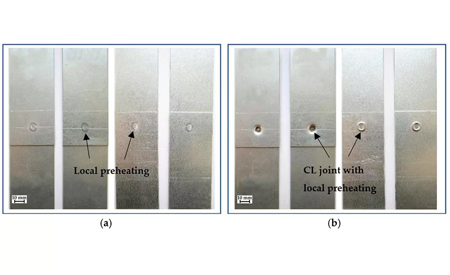
In our process, we overlapped two sheet metal coupons and applied intense local heat to the area to be clinched. Heat was supplied by spot welding electrodes that were 8 millimeters in diameter. The following parameters were used to heat the joint: Current was 3.9 kiloamps; time was 0.72 second; and pressing force was 6 kilonewtons.
Our goal was solely to achieve a change in the microstructure in the neck region of the joint during clinching. A spot weld with a typical weld nugget was not allowed to form.
After heating, the samples were immediately clinched using a punch 5 millimeters in diameter and a die 8 millimeters in diameter. The pressing force was 80 kilonewtons.
After clinching, we performed tensile shear testing to measure the load-bearing capacity of the assemblies. We also examined the joints using light and scanning electron microscopy, and we conducted microhardness measurements on the joints.

All About Clinching
Creating a clinched joint consists of the following steps: clamping, pressing, bottom-forming, and interlock-forming. Pre-forming the parts has a significant impact on the outcome of the joining process. Particularly, the pre-forming of the material on the punch side has a greater influence on the joining parameters compared to the material on the die side.
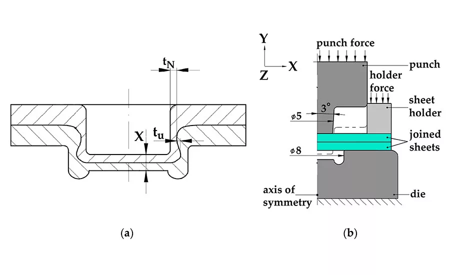
The thickness of the neck (tN), the joint bottom thickness (X) and interlock (tu) are the main parameters that determine the load-bearing capacity of a clinched joint. We used numerical simulation software to identify the zones in the sheet metal that are moved to the area of the neck of the clinched joint.
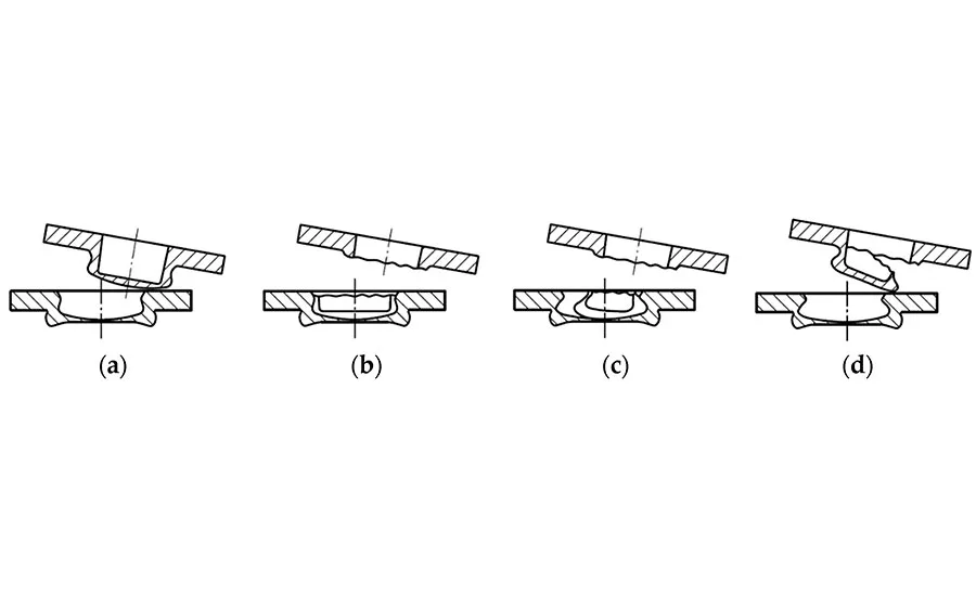

The failure modes of clinched joints include pull-out, neck fracture, neck fracture with plastic deformation, and pull-out with neck fracture. The two most common failure modes are pull-out and neck fracture.
Pull-out involves the complete separation of the upper and lower sheets. This mode is characterized by a lack of sufficient geometric interlocking in the joint. When subjected to tensile-shear loading, the two sheets experience plastic deformation and eventually slide apart when the strength of the interlock becomes weaker than the applied tensile load.
Neck fracture is characterized by a fracture occurring in the thinnest part of the upper sheet’s neck. When subjected to tensile-shear loading, a force is applied to the neck of the upper sheet in a shearing motion. As the load increases, the shearing force on the thinnest part of the neck gradually increases. Eventually, when the neck becomes thinner, a ring fracture occurs once the shearing force reaches the strength of the thinnest neck.
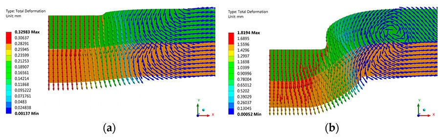
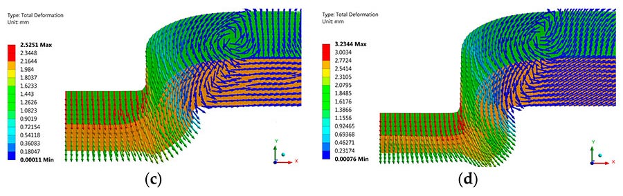
These images show our numerical simulation of material flow during clinching process: (a) clamping, (b) pressing, (c) bottom-forming, (d) interlock-forming. | Illustration courtesy Technical University of Košice
The Clinched Joints
To increase the load-bearing capacity of clinched joints, it’s important that the hardened structure of the preheated material reach the neck of the joint during clinching.
Our clinched joints in both materials showed an intense thinning of the thickness of the sheets in the area of the neck. In the joint made with HCT600, the microhardness was around 300 HV0.3 at the base of the joint and 350 HV0.3 at the neck. In the joint made with HX420LAD, the microhardness was around 250 HV0.3 at the base of the joint and 300 HV0.3 at the neck.
The localized preheating changed the microstructure of the base materials. For HCT600, the microstructure changed from the original ferritic-martensitic microstructure to a gradient fine-grained ferritic-sorbitic microstructure. These changes were observed in both sheets. Similarly, for HX420LAD, the microstructure changed from the original ferritic-perlitic microstructure to a gradient fine-grained ferritic-sorbitic microstructure.


More importantly, the stronger microstructures were observed in the center, corner and neck regions of the joints—precisely where they are needed most to increase joint strength.
Next, we compared the load-bearing capacity of standard clinched joints with our preheated clinched joints. For both types of steel, a higher load-bearing capacity was obtained for the preheated clinched joints.
With HCT600, the load-bearing capacity of standard clinched joints ranged from 5,398 to 5,540 newtons. In comparison, the load-bearing capacity of the preheated clinched joints ranged from 6,227 to 6,525 newtons. In short, load-bearing capacity was higher by an average of 17 percent.
With HX420LAD, the load-bearing capacity of standard clinched joints ranged from 3,712 to 3,831 newtons. In comparison, the load-bearing capacity of the preheated clinched joints ranged from 4,224 to 5,200 newtons. In short, load-bearing capacity was higher by an average of 25 percent.
The increase in the load-bearing capacity of the preheated clinched joints is related to the change in the microstructure of the material in the joint. The microhardness values throughout the joint were higher in the preheated clinched joints in both types of steel.
Looking at failure modes, cracked necks with plastic deformation often occurred in both types of steel with standard clinching. This is typical when the strength of the interlock is slightly greater than that of the clinched neck.
However, after application of local heating, the failure mode of the clinched joints was most commonly neck fracture. An increase in the hardness of the neck zone of the preheated clinched joints resulted in an increase in the strength of the material.
Conclusions
Based on our experiments, the following conclusions can be stated:
In the entire clinched joint, no discontinuities were observed in the material by light and scanning electron microscopy.
Fine-grained ferritic-sorbitic and fine-grained sorbitic microstructures were observed in the clinched joint at the neck when local heating was used.
Preheating the metals prior to clinching increased the load-carrying capacity of the joints by an average of 17 percent for HCT 600X and by an average of 25 percent for HX420LAD.
It’s important to note, however, that our experiments involved sheets 1.5 millimeters thick. Thicker sheets would require more energy for heating, which can negatively affect the zinc layer on the surface. At elevated temperatures, degradation of the coating may occur, which could adversely affect the corrosion resistance of the joints.
In addition, we did not consider the joining of ferrous and nonferrous metals, such as steel to aluminum. Due to the different melting temperatures of two metals, it would be difficult to achieve a local change in the microstructure.
Editor’s note: This article is a summary of a research paper co-authored by Miroslav Dzupon, Slovak Academy of Sciences, Kosice, Slovakia; Denis Cmorej, Technical University of Kosice; Lucia Ciripova, Slovak Academy of Sciences; Jacek Mucha, Rzeszow University of Technology, Rzeszow, Poland; and Emil Spisak, Technical University of Kosice. To read the entire paper, click here.
ASSEMBLY ONLINE
For more information on sheet metal assembly, read these articles:
Clinching for Galvanized Sheet Metal
Techniques for Joining Sheet Metal
Clinching for Electrical Assemblies
Looking for a reprint of this article?
From high-res PDFs to custom plaques, order your copy today!


