Flow Testing Instruments Help Automotive Supplier Meet Quality Specs
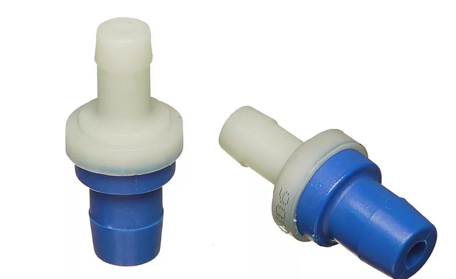
Automotive PCV (positive crankcase ventilation) valves appear to be such simple devices. They’re small, with only one moving part and a spring inside. Nevertheless, they must meet surprisingly rigorous performance specifications to win approval from OEMs. Valve suppliers must document that every valve design will reliably permit specific amounts of airflow at specific vacuum levels.
For Novo Products Inc., satisfying these requirements went beyond learning new techniques for vacuum and flow testing. When customers began requesting test data on prototypes presented in graphic form, we had to find test capabilities that no known instrument could provide. We ultimately met that challenge—and cut design time significantly—with a customized combination of mass-flow leak-tester and PC-based test-networking software.
No stranger to stringent component specifications, Novo has been serving the automotive industry since 1973. The company has built itself into a leading Tier 2 and Tier 3 supplier of emission control devices, fuel delivery components and electronic engine controls, and it has earned ISO and QS 9000 certification along the way. When the opportunity to solve one automaker’s PCV valve failure problem came along in 1999, we sensed a long-term business opportunity. These inexpensive parts offered the potential for high-volume sales. Today, Novo produces more than 4 million PCV valves per year in seven designs.
Flow testing is vital because PCV valves must relieve engine crankcase pressure correctly to prevent backfiring or blown gaskets and seals. To do this, they regulate pressure outflow from the engine by means of a tapered poppet moving in and out of a tapered orifice. The orifice outlet is connected by tubing to the engine’s air-fuel intake. Vacuum generated by the air-fuel intake modulates the poppet. Spring tension holds the poppet open when vacuum is low, but allows increasing vacuum to gradually pull the poppet closed. When the poppet is open and engine gases are venting, the tubing and low vacuum channel those emissions back into the air-fuel intake so they can be reburned rather than vented to the atmosphere as a pollutant.
Each engine design has a different relationship between the amount of vacuum and the amount of crankcase pressure allowed to vent. That relationship, in turn, requires each PCV valve design to have a unique balance among the geometry of the poppet and orifice, the force of the spring, and the level of vacuum.
Customer specifications define the valve’s external size and shape, along with flow values desired at designated vacuum levels, termed "delta points." For PCV valves, vacuum typically ranges from 1 to 20 inches of mercury, while flow values might be anywhere between 0.2 and 8 cfm. Novo engineers are left to determine the internal design needed to achieve the desired performance.
Largely Trial and Error
We’ve never been able to develop a formula for designing a PCV valve. It’s largely trial and error, so the prototyping process can be time-consuming. We start with a design that experience suggests should meet the requirements. We test it against the customer’s specs, make changes, and test again. We keep repeating that process until we nail it.For quality control testing during production, buyers will specify flow at three delta points. However, before authorizing production of a prototype design, buyers usually want to see the valve’s performance verified by a more definitive curve that plots flows from up to 20 points.
Meeting specs like these was our first brush with flow testing. We have vast experience in doing sophisticated leak-rate testing of fuel system components, but that’s different. There, it’s a matter of pressurizing the product and measuring the rate at which air leaks out. Typically, that’s a production line test done to verify the integrity of formed or assembled parts. While PCV valves are also tested during production, prototype testing is critical because that’s what guides development of the valve’s internal geometry. This up-front test procedure is far more intricate.
Looking for quick answers on assembly and manufacturing topics? Try Ask ASM, our new smart AI search tool. Ask ASM
One complicating factor is the time needed to let airflow stabilize at each vacuum point before the flow is measured. Other complicating factors are the airflow’s absolute pressure (psia) and temperature, because these values will cause both vacuum pressure and air density to vary. Some buyers will base their vacuum and flow specs on standard atmospheric pressure of 14.7 psia at 20 C. Others prefer different ambient pressure and temperature baselines that they consider more representative of normal operating conditions. Our flow-testing instruments must report test data corrected to show flow as it would be under whatever standard conditions the buyer specifies.
Homemade Tester Tried
For our first foray into flow testing, we tried building equipment and fixtures in-house. We tried combining a simple commercial flow meter with our own valving system. It worked, but manual data gathering was time-consuming. We weren’t sure about its accuracy, and we needed something better to double-check our method. For that, we called on InterTech Development Co. (IDC), a company that had provided us with several turnkey assembly systems with integrated leak-testing functions for fuel system products. Intertech also supplied leak testing instruments and consultation for several proprietary leak test stands that we built in-house.Collaborating with InterTech, we built a two-station machine. Each station has two test fixtures: one for valves operating in the 0.2 to 2 cfm range, the other for valves operating in the 2 to 6 cfm range. Low-flow and high-flow fixtures on both stations are connected alternately to a pair of InterTech M-1035 mass-flow instruments. One M-1035 is equipped with a mass-flow transducer covering the lower range, while the other’s transducer covers the higher range. Both instruments are equipped with programmable vacuum regulators covering a range of 1 to 20 inches of mercury.
In a typical production test, the PCV valve remains in the same fixture while the M-1035 sequences through three programs, one for each of the specified vacuum delta points. Arriving at each point, the instrument pauses for a prescribed stabilization time, then measures the rate of airflow through the valve. Each delta point test typically takes about 12 seconds, for a total part-to-part test cycle of 36 seconds.
In each test, air drawn through the valve by the vacuum is channeled across the M-1035’s transducer, producing an output voltage proportional to its mass flow, which the instrument electronically translates and displays as an almost instantaneous single-point flow-rate measurement. It also displays vacuum pressures during the test, compares both pressure and flow against preset limits, and signals the operator to accept or reject the part. No operator judgment or external calculations are needed.
The dual-fixture, dual-station, dual-instrument setup enables one fixture in each station to be testing while its counterpart in the other station is manually unloaded and reloaded. The second fixture in each station allows a different part with a different set of programs to be tested simultaneously.
By using stationary fixtures, with each test instrument switched back and forth between stations by PLC-controlled valves, we avoided the higher cost of automatic moving fixtures along with the cost of safety devices that moving fixtures would require. Whenever a valve fails its test, the M-1035 prevents the PLC from switching to the alternate fixture until the operator acknowledges the reject.
Records Kept Automatically
Programmed to treat each delta point measurement as a separate test, the M-1035s automatically save vacuum, flow and pass-fail records for their last 1,000 tests (333 valves). These records can be printed out for repeatability and reproducibility studies or to evaluate any anomaly in reject rates. The instruments also have on-board memory to store 100 test programs, so each instrument can accept enough three-program sequences for 22 valve designs. This accommodates Novo’s seven-valve family with room to spare for future product line growth.With its ability to recall test data and to program precise vacuum points and flow limits, the production tester became the instrument-of-choice for prototype testing, as well. When new valve designs began requiring 20-point curves spanning both low- and high- flow ranges, we would test the low-flow and high-flow delta points on whichever M-1035 had the appropriate transducer. We’d then collect the data from both tests, and manually plot the curve by patching the segments together. However, that wasn’t the best way to do it, because it puts a void in the curve wherever the data jump from one instrument to the other. In addition, it was always possible that the combined data didn’t reflect identical calibration in both instruments. Still, it was better than anything else we had at the time.
Six months after start-up, production of the high-flow valve ended temporarily, so the high-flow production instrument was refitted with a low-flow transducer to provide more testing capacity for the increasing volume of valves in that range. With that, the only way we could do full-curve prototype testing was to fill in the missing range points with our old homemade tester, which made the task more difficult and less reliable. It became obvious that to seriously pursue this business, we needed a full-range tester and a better way to analyze and visualize the data. The problem was, it didn’t exist.
Customized Lab Tester Created
To solve the problem, InterTech proposed a customized version of the M-1035 that we were using in our production test stand. Its mass-flow transducer was replaced with an external laminar flow element having a master lab calibration accuracy of ±0.6 percent of reading across the desired flow range of 0.2 to 8 cfm. This would be coupled with an airflow temperature sensor, a high-accuracy differential pressure transducer certified at 0.15 percent of reading, and a high-accuracy absolute pressure transducer certified for 0.3 percent of reading.The M-1035s in production testing provide mass-flow transducer accuracy of ±0.5 percent of range, which satisfies our accuracy requirements over their relatively short airflow ranges. However, percent of reading capabilities are essential in their lab counterpart to ensure consistently high accuracy at all points along the instrument’s ex-tended airflow range. Adding the high-accuracy transducers and temperature sensor, along with custom programming, enables the lab’s M-1035 to measure flow values at ambient temperature and pressure, but display and record them as corrected to buyer-specified standard conditions.
Test program and data storage, which usually reside inside a standard M-1035 in conventional applications, was shifted to an external laptop PC running a customized version of InterTech’s S-3085 monitor software.
Normally used to network up to 34 leak-testing instruments for supervision by a remote host computer, the S-3085 software was conceived for better management of multistation testing operations, quality control and statistical process control programs, and traceability documentation. Adapting it for our lab testing requirements, IDC modified this package to let the PC accept and store test parameters for up to 20 delta points for each PCV valve design, including calculations for correcting atmospheric pressure and temperature to buyer specifications. Additional software customization allows the PC to display real-time test results for all delta point tests combined into a single continuous graph, depicting changes in both vacuum level and airflow over time against each point’s upper and lower accept and reject limits. Using a PC for this task allows complete, full-range curves to be seen on a single screen. In addition, the data can be exported to Microsoft Excel, printed out, and even e-mailed directly to customers.
PC Increases Capacity
Adding the PC served other essential purposes as well. While a standard M-1035 can store and recall enough test programs for up to 33 three-point production tests, the lab tester needed greater storage capacity. Because each delta point test requires a separate test program, 20-point tests for each of seven PCV valve models tallies 140 programs. And, that total is certain to grow as more valve models come into our product mix.Although a standard M-1035 automatically stores data from its last 1,000 tests, the S-3085 software enables the lab tester’s PC to store much larger amounts of test data, by date, in a Microsoft Access database, at 2 mil-lion test records per 100 megabytes of space. It also allows the PC to recall stored test data either in total or using selection filters, such as date, accept or reject results, or reject causes (e.g., high or low pressure). Exported to Microsoft Excel, test data for multiple samples of the same prototype can be merged for presentation comparing average flow performance vs. high or low extremes across the sample population.
The lab unit’s test functions are controlled by the M-1035. Custom programming enables the instrument to receive the multipoint program for a specific PCV valve from the PC. The instrument can then sequence through the test for each delta point while sending real-time test data back to the PC for display and storage. Each delta point’s test program starts by ramping the M-1035’s programmable vacuum generator to approximate target level, followed by closed-loop adjustment to reach a precise level. The instrument then pauses for a prescribed stabilization time, reads the transducers, measures the flow, corrects the measurement per the customer’s standard conditions, compares that with the specified limits, decides to accept or reject the part, and advances to the next delta point test program.
Speeds Design, Boosts Productivity
The IDC system has greatly accelerated the task of prototype testing. It has cut our actual testing time by 40 percent to 50 percent, largely because it’s a dedicated lab instrument. We no longer need to wait for a break in productionor worse, interrupt it. Using the production testers for design work wasted time with tooling and program changeovers for the test parts, then changing everything back to resume production testing. It also required a much more extensive calibration procedure.With the new testing equipment, the total time needed to design a new PCV valve is typically reduced by about 20 percent. That’s because the data is more accurate and because its presented in curves that make the data easier to interpret. Real-time graphic display lets us see and document in greater detail exactly how a design is behaving at all Arial during its cycle. We no longer have to plot curves manually or patch curves together. This, in turn, gives us better direction and helps us respond more quickly with design, tooling and equipment adjustments.
Manufacturing PCV valves is not difficult. The hard part is the design and prototyping stage, and there, the quality of the testing is what separates a premium product from a commodity. Our new system makes it easier to meet the differing standards of automotive customers precisely.
The benefit of better design testing also trickles down to productivity. Customers don’t specify stabilization time, so while we’re tweaking a new design’s internal geometry to achieve the flow spec, we also can try alternatives in springs and poppet designs to shorten the stabilizing time, as well. Shorter stabilizing time allows faster part-to-part cycles when the part is tested during production.
The customized IDC system also gives us a better tool for studying any abnormal failure rate appearing in production valves, and for evaluating the design of competitive products. In addition, the S-3085 software enables the PC to reprocess the stored data into histogram or trend charts for statistical evaluations.
Looking for a reprint of this article?
From high-res PDFs to custom plaques, order your copy today!


