Assembly Handbook: Blind Riveting

In the world of politics, a person who's one-sided usually isn't too popular with too many people. However, in the realm of fasteners, blind rivets are extremely appealing because of their one-sided characteristics.
Blind rivets are permanently installed fasteners that sometimes exceed the performance criteria for comparable solid rivets. Unlike solid rivets, blind rivets can be inserted and fully installed in a joint from only one side of a part or structure, "blind" to the opposite side. The back, or blind side, is mechanically expanded to form a bulb or upset head. Because blind rivets are installed from only one side of the component, they are cost-efficient and versatile.
The blind rivet was originally developed as a replacement fastener for solid rivets where service repair was required. Blind rivets also trace their roots to the aircraft industry. Before blind rivets were widely accepted, installation of solid aluminum rivets in fuselages, wings and other airframe components typically required two assemblers: one person with a rivet hammer on one side of the structure and a second person with a bucking bar on the other side. Since rivets were often inaccessible from both sides of the work, this assembly process was extremely slow and very time consuming.
The pop rivet was invented in Scotland shortly before World War I. In the United States, inventors such as Carl Cherry and Lou Huck experimented with other techniques for expanding solid rivets, such as the pull-through method. By drilling a hole through a rivet and expanding it with a mandrel, these fastener pioneers eventually developed a cost-effective rivet that could be installed in structures where fasteners were accessible from one side only.
The first steel blind rivets were developed for use in the auto industry during the Great Depression. Another early blind riveting application was the assembly of power rotors--a rotating cylinder placed on top of a tower to harness wind--used to generate electricity on farms.
In 1939, the first U.S. patent was issued for an aluminum blind rivet. It was quickly adopted by the aircraft industry. The device enabled mass production of military aircraft during World War II.
Today, blind rivets offer numerous benefits to assemblers, such as speed of installation, versatility, simplicity and cost. Unlike many other fasteners, blind rivets cannot be under-torqued, over-torqued or set loose. The unique design and function of blind rivets prevents these errors.
Looking for quick answers on assembly and manufacturing topics? Try Ask ASM, our new smart AI search tool. Ask ASM
How They Work
A blind rivet is a two-piece fastener that consists of a headed, hollow rivet body and a solid mandrel. The body, or sleeve, looks like a small tube that is flared on one end. The tube portion is called the shank and the flared portion is called the head.The rivet body is usually round. The diameter of the rivet body determines the rivet size. A hole, or core, usually extends the length of the body. However, the extent of the core depends on the rivet style.
The mandrel is the mating section of the rivet body, also known as the stem, which protrudes from the rivet core. It looks like a nail or wire, and is pulled through the joint of a blind rivet hole during setting.
The rivet body is inserted in a hole in the parts to be joined. Next, the jaws or nosepiece of a manual or automated rivet tool grips the mandrel. As the tool begins to pull the mandrel head into the rivet body, the body expands and forms a joint. Pulling on the mandrel with a rivet tool deforms the tail end of the rivet body, forming a blind-side head. At a predetermined setting force or tensile load, the mandrel breaks and falls away. The blind head is the rivet body portion on the blind side after the rivet has been set.
Unlike many other fasteners that require access to both sides, a blind rivet can be set from one side of the work. The ability to set blind rivets without the need for access at the back of the workpiece makes their use mandatory in many instances.
Blind rivets are commonly associated with the aircraft industry. However, they are also used in a wide variety of products, such as air bag assemblies, telecommunication equipment cabinets, stoves, air conditioners, garage doors, prefabricated metal buildings and mail boxes. Bus, truck, railcar and recreational vehicle assemblers are heavy users of blind rivets. Electronics manufacturers are also using more blind rivets for box-build applications.
Increased use of composite materials, such as plastic, fiberglass and plywood, has increased demand for blind rivets with different upset styles to fasten those materials. These rivets expand like the petals of a flower on the back side of the material, so the clamping force is spread out.
Multiple Choices
Blind rivets are available in a wide variety of materials, diameters, grip ranges and head styles. Material choices include aluminum, steel, stainless steel, copper, brass and plastic. Blind rivets are commonly classified as either pull-type or drive-pin-type fasteners.Pull mandrel or pull-up rivets have a hollow core rivet body and an integral mandrel. The mating mandrel is positioned in the rivet body, which includes a preformed head with the mandrel extending above the rivet head.
The mandrel end that protrudes from the rivet end flares out to a larger diameter than the diameter of the rivet body core. When the mandrel is pulled up after the rivet is inserted, it forces the rivet material out against the back of the assembly. This clamps the parts between the rivet head and the new-formed head on the blind side.
The pull-type blind rivet is available in two basic configurations: self-plugging and pull-through. In the self-plugging design, a portion of the mandrel is permanently retained in the rivet body, contributing additional shear-strength properties to the installed fastener. The self-plugging blind rivet is typically used for structural applications where higher fastener shear strength is necessary because of joint design loadings.
In the pull-through blind rivet, the mandrel is completely drawn through the rivet body after expanding the rivet. It is typically used for lightly loaded or nonstructural joining applications.
A break-mandrel rivet is the most common type of pull-mandrel blind rivet. During the setting operation, the mandrel is pulled into or against the rivet body and breaks, causing a popping sound. Break mandrel rivets are available in two styles: semifilled core and filled core.
Semifilled core rivets, also called nonstructural, break the mandrel near the blind-side head, leaving a short length of mandrel in the rivet body and the core partially filled. Filled core, or structural rivets, have a mandrel that fills the entire core and usually breaks near flush with the surface.
A drive-pin blind rivet includes a partial hole in the rivet body and a mating, protruding pin that is positioned in the hole. In the setting operation, the rivet is inserted into the components to be joined. The pin is hammer driven into the rivet body until the pin is flush with the top of the rivet head.
Common styles of blind rivets include N-, Q- and T-types. The N, or nail rivet, features a break mandrel and semifilled core. It is often used to tack light sheets together where minimal stresses are exerted.
The Q-type rivet features a break mandrel and filled core. It's similar to the N-type rivet, except that the mandrel neck is knurled to lock the mandrel in the rivet body and assist in creating a seal. The mandrel breaks relatively flush with the rivet head in midgrip, increasing shear strength. The Q-type rivet is used in applications that require shear strength greater than that provided by an N rivet.
The T-type, or peel, rivet features a break mandrel and filled core. During installation, knife action between the mandrel head and rivet shank splits the rivet into three "petals" that draw the sheets together. A T rivet mandrel breaks nearly flush with the rivet head in maximum grip. Because it's insensitive to hole size, the T-type rivet works in oversized or elliptical holes.
Many variations of blind rivets are available, such as the one-piece nut rivet that features internal threads. It provides load-bearing female threads for attaching removable parts in material that may be too thin to accommodate a thread.
Other types of blind fasteners include locking and drive rivets. Locking rivets are vibration resistant and are less prone to failure in high shear loads. Drive rivets can be used in through-hole applications to fasten metal sheets, or in blind-hole applications to fasten wood and other low-density materials.
Selection Criteria
Factors such as joint strength, joint thickness, materials, hole size and head style must be considered before selecting a blind rivet.
The single-joint tensile and shear values required for the application must be determined. These are functions of total joint strength, fastener spacing, rivet body material and rivet diameters.
The total thickness of the materials to be joined must also be determined. This reveals the required grip of the rivet to select. Insufficient rivet length will not allow correct formation of the secondary head at the back of the work.
Both the rivet and the materials to be fastened will affect the ultimate joint strength. As a general rule, the rivet materials should have the same physical and mechanical properties as the materials to be fastened. A marked dissimilarity may cause joint failure due either to material fatigue or galvanic corrosion.
Strength and durability are very important considerations when choosing blind rivets. For the blind rivet system to work, the pull mandrel or drive pin must be stronger than the rivet body, which must be relatively ductile to permit blind end expansion without cracking.
Blind rivet strength varies depending on the materials used and the specific type or design of fastener. If the joint needs to be very strong, a steel rivet works best. On the other hand, plastic rivets may not be the best choice for an application, because they tend to dry out and get brittle.
Hole size is very important in blind riveting. An undersized hole will make rivet insertion difficult or impossible. Too large a hole will reduce the shear and tensile strengths, and may cause incorrect rivet setting. It may also cause bulging or separation of the members by allowing the rivet to expand between them instead of on the blind side. It is important to avoid burrs in and around the hole.
Three different head styles are available for blind rivets: dome, large flange and countersunk.
Dome head rivets, also called buttonheads, are the most versatile and most commonly specified head style. This type of fastener features a low profile and a neat appearance. The dome head has twice the diameter of the rivet body, providing enough bearing surface to retain all but extremely soft or brittle materials.
Large flange rivets have twice the under-head bearing surfaces of dome head rivets. They are typically used for applications where soft or brittle materials must be joined to a rigid backing material.
Countersunk rivets should be specified whenever a flush surface is required.
Installation Tools
Blind rivets require installation tools that hold the body in place while the mandrel is pulled into or through the rivet. A wide variety of manual, hydraulic, pneumatic and electric tools are available. Various pulling heads and nosepieces are also available for different riveting applications.Pliers-like hand tools are very common, but are generally limited to installation of smaller diameter sizes, or to blind rivets fabricated from softer materials. However, manual tools provide light weight and versatility. Hand tools are also available for removing blind rivets and trimming excess mandrel.
Until recently, blind riveting was primarily a manual process. But, automated tools offer greater pulling capacity. Many of these tools have also become lighter, more powerful and more ergonomic. For instance, some tools feature a built-in shock absorber that reduces the kick created when a rivet is set.
Another ergonomic improvement is the development of riveters with long strokes. Long-stroke tools deliver power over a longer distance, resulting in less end-of-stroke exertion by the tool and operator. A long-stroke tool transfers power more efficiently on longer, more difficult rivets or materials.
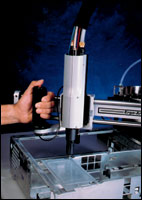
Automated tools include in-line or vertical riveters and pistol-grip rivet guns. Traditional pistol-grip tools are designed for use in a horizontal plane. In-line riveters provide an option for vertical riveting applications. They can be hung from a counterbalance, just like an in-line screwdriver. More fixed, semiautomatic workstations are also being used to feed and insert rivets.
Riveters can be equipped with multiple heads for installing more than one fastener at a time. Tools can also be supplied with automatic feeding units that hold several thousand rivets. Vacuum systems in the riveting head suck spent mandrels into a container after the rivet is set.
Problem Solving Tips
Assemblers can maximize their use of blind rivets and avoid headaches by following a few basic tips. For example, it's important to always set the rivet so that its blind side is against the thicker material being joined. This allows the rivet head to distribute more bearing surface over the thinner material.Because a blind rivet is inserted from only one side of the structure, a potion of the rivet body and mandrel will extend beyond the blind side of the work being assembled. The backside clearance is the distance the blind rivet protrudes beyond the structure. Backside clearance varies, depending on rivet style and diameter. Adequate room should be provided to include the backside clearance for the blind rivet.
A common problem that occurs when using blind rivets is mandrel pull through. When this happens, it leaves a burr outside of the eyelet flange. This problem can be resolved by drilling or punching the correct specified hole size for the rivet. When the recommended hole size is exceeded, the mandrel head of the rivet can drag its way through the rivet body.
Another cause of rivet pull through is using a rivet below the minimum grip range. A pull-through is more likely to occur in rivets that have smaller size grip ranges.
As with solid rivets, blind rivets should not be positioned too close to the edge of a joint subjected to structural loading. The centerline of the rivet hole should be at least equal to the diameter of the rivet.
In a standard blind rivet, a piece of the mandrel is left inside the body when the mandrel breaks. Over time, there's a possibility that the leftover mandrel could shake loose. It won't affect the strength of the rivet, but it could cause a pesky noise, especially if the rivet is exposed to vibration. Closed-end rivets can avoid that problem.
In a closed-end rivet, the mandrel and ball are inside the body. The end of the rivet is sealed. Closed-end rivets also prevent the passage of vapor or liquid through the placed fastener. They offer greater shear and tensile strength than open-end rivets. Closed-end rivets are ideal for electric or electronic assembly applications.
One of the most common problems that occurs when using a hand- or air-operated threaded-insert setting tool is the breakage of the mandrel or stripping of insert threads during the setting process. Each threaded insert has a very specific grip range associated with its thread size. The grip range is the total thickness of the material that the threaded insert will be set into.
For example, if you are setting a threaded insert into a 0.21-inch thick material, you must select a threaded insert that has a grip range that covers the same thickness. A threaded insert indicating a grip range of 0.125 to 0.25 inch would be the correct choice.
Resources
ASSEMBLY would like to thank the following companies for their contributions: Allfast Fastening Systems Inc.; American Society of Mechanical Engineers; Atlas Engineering Inc.; Avdel Cherry Textron Inc.; Celus Fasteners Manufacturing Inc.; Emhart Fastening Teknologies; Gesipa Fasteners USA Inc.; Huck International Inc.; Industrial Fasteners Institute; Lobtex Co.; and Marson CorpLooking for a reprint of this article?
From high-res PDFs to custom plaques, order your copy today!


