Inspection: Detecting Missing Bearings
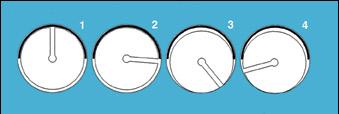
The hydraulic test measured oil pressure with the crankshaft driven at 30 rpm by a servomotor. Another servomotor turned the oil pump to generate oil pressure. Oil pressure readings were taken at every 90 degrees of crankshaft rotation and compared with set limits.
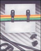
This test verified that 31 bearings were correctly assembled in the engine. The bearings are five camshaft bearings, 10 crankshaft bearings and 16 connecting rod bearings. The test was performed after the heads and oil pan were installed, and the engine oil pan was filled with oil. If one or more missing bearings were detected, the engine was drained, the heads and oil pan removed, and missing bearings installed. Teardown and repair was time-consuming and messy.
Testing With Air
The objective was to find a dry test method that could be performed immediately after bearing installation. Repairs would be simpler and cleaner, and the assembly team would receive immediate feedback regarding process quality. GEP approached InQuest, the testing division of Cincinnati Test Systems (Cleves, OH), regarding dry testing the partially assembled engines.To prove the concept of converting the oil test to a similar air test, trial tests were conducted by pressurizing the oil galleries in an assembled engine with air instead of oil.
A steady flow of air is fed into the engine's oil galleries. The air flows through the camshaft bearings to the main bearings, around the block-side bearing to the oil spray nozzles, and through the crankshaft to the connecting rod bearings. The measured back pressure signature of the air correlates to the angular rotation of the crankshaft. The initial study performed on three engines showed some promise. However, studying multiple engines showed that the part-to-part signature variation was too large to detect missing bearings reliably.
Inconsistencies in the air signature tests prompted a sound signature test. With the oil gallery pressurized and the engine turning at a slow rpm, a change in pitch occurs as an oil passage opens up to where a bearing is missing. A connecting rod oil passage is blocked as the crankshaft pin pushes the connecting rod up. As the crankshaft turns past top-dead-center and starts the downward stroke, a change in pitch occurs as an opening develops between the connecting rod bearing and the crankshaft pin. As the crankshaft pin continues down, the oil passage reseals against the connecting rod bearing, and the sound is minimized. As the crankshaft pin starts its upward swing, an opening between the crankshaft pin and the connecting rod bearing develops again. However, there is no sound, because oil (pressurized air in the test) is only supplied for 180 degrees of crankshaft rotation.
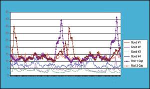
A single microphone sound analyzer with a third octave spectrogram was used for a series of tests determining feasibility. The relative timing of the readings was determined from the number of readings between the start and the stop of the test at an angular position. The microphone was mounted on a multi-manipulative arm, so it could be positioned at various locations around the crankshaft to determine the best sound reading area. Sound signatures were recorded from a virgin engine (an engine with all bearings known to be correctly installed and previously tested) and then compared with signatures from engines without certain bearings. The engine was again tested with all bearings installed to determine if any change occurred from the virgin engine signature.
A third octave spectrum analyzer divides sound into 16 frequency bands. The lowest band ranges from 0.8 to 2 kilohertz, with the highest being 19.2 to 20 kilohertz. Missing bearings emit most sound energy in the 6.8 to 9.2 kilohertz and the 17.6 to 20 kilohertz bands. Missing cam and crankshaft bearings consistently generate more noise. If the case side main bearing is missing, the sound pitch changes as the oil path to the connecting rods passes by the case supply hole.
Looking for quick answers on assembly and manufacturing topics? Try Ask ASM, our new smart AI search tool. Ask ASM
Production Testing
GEP ordered two systems to cover production and off-line repair. The first unit was supplied early to further define part signatures and lay out production hose and cable lengths. Three engines were built, confirmed as good, and tested as good virgin engines. Each bearing was removed, and the engines were tested again. The data from the three engines was compared and a reject point determined as a sound level at a given angular position. Large amounts of data had to be deciphered and correlated to determine the signatures that defined an acceptable engine. A set of VBA applications running in Excel to speed up the process and graphically display the information was developed. This process revealed that a peak value was not sufficient to find all rejects. To eliminate background noise from the spray nozzles, a valley-to-peak check was added.One microphone per pair of connecting rods is needed to pick up the signatures. A PC-based system also stores the data and performs the data manipulation and transfer. Data collection and manipulation includes performing a third octave spectrum analysis calculation on four microphones. The calculations are correlated to the angle of crankshaft rotation. The results are compared to an engine model preset table to determine if a bearing is missing.
The engine rides on an industrial engine cart pulled by a chain in the floor. The sound hood, drive motor, cables and hoses are suspended from counter balances and a trolley system that travel with the engine during the test.
An adjustable grid arrangement defines bearing signatures, which makes the system usable by a lay person and reconfigurable in the field. Each bearing signature can be defined as an angular range to an upper or lower frequency spike. Different model engines can be defined and changes made in the field to further clarify the engines' signatures.
The initial goal was to provide a simple, clean and adaptable test system for a new low-volume assembly line. The new dry test system meets this goal, along with:
- providing immediate feedback of correct bearing installation by reducing feedback loop (number of engines assembled prior to testing) parts installed from 39 to one before inspection;
- providing field-settable reject limits and messages for each bearing;
- reducing test equipment cost;
- detecting foreign objects in assembled engines;
- detecting blocked oil paths that were previously undetected;
- minimizing engine rework;
- providing an environmentally friendly workplace;
- improving operator safety;
- evaluating stored engine test data if new problems occur; and
- reducing customer complaints and warranty issues
Looking for a reprint of this article?
From high-res PDFs to custom plaques, order your copy today!


