Like the proverbial chain, an assembly line or process is only as strong as its weakest link, and nowhere is this truer than when dispensing one-part materials, like liquids, pastes and gels. Except for those most basic applications, an efficient dispensing system includes a variety of components working together in harmony, all configured to deliver a specific quantity of a specific material to a specific place at a specific time.
Central to this process is the correct valve. At first glance, many of the various valves used in industrial dispensing may appear to be pretty much the same. However, the reality of the situation couldn’t be more different. Not only are valves available in a number of different materials-especially their wetted parts-employing a variety of different materials in their seals, they also use a number of different approaches to turning on and off the flow of material.
And we’re not just talking about servo-driven vs. pneumatically powered valves here. Needle valves, piston valves, ball-and-seat valves, spool valves, diaphragm valves, auger valves: Assemblers have a range of different technologies to choose from, depending on the type of material they are working with and the type of product they are building.
“Today, there are more materials available than ever before,” says Mark Ruhlmann, dispense valve division manager at Sealant Equipment & Engineering Inc. (Plymouth, MI). “When a customer asks about a dispense valve for their application, we request material and process-specific questions, which allow us to clearly define the conditions the dispense valve will be working in. We can therefore recommend a dispense valve that will perform in the customer’s process environment.”
Among these various material and process-specific questions, one of the most important is that of viscosity. This is true not just because of the physical requirements involved in controlling the material as it passes through the body of the valve. It is also vital that you employ the correct type of valve to ensure you don’t have dripping material between shots making a mess of work-in-progress.
Equally important is the amount of material you need to dispense, and the precision and speed with which you need to execute this dispensing. Obviously, placing a small drop of adhesive to secure a hypodermic needle assembly is a far different matter from encapsulating electronic components or laying a bead of sealant in an automotive transmission assembly.
Then there is the question of the makeup of the material itself. Is it corrosive? Does it contain an abrasive filler that is going to clog up a small orifice or take a toll on a conventional valve housing and seals. Will the material require continual cleaning or the replacement of disposable valve parts?
Finally, it may be necessary to take into account the unusual ways some fluids behave under pressure. For example, some gels will become liquid when disturbed, while some liquids will develop strange flow patterns that have to be accommodated for.
“Understanding the rheology of the material is very important in selecting the valve,” says Don Leone, general manager at Ashby Cross Co. (Newburyport, MA). “How the fluid reacts under pressure, viscosity, temperature effects, shear effects and flow characteristics [all] influence the valve selected.”
“No two applications are exactly the same,” agrees Claude Bergeron, business development director at EFD Inc. (East Providence, RI), adding that valve choice is especially critical in a high-speed, automated environment. “The last thing you want is a lot of down time or to produce a lot of bad parts because the dispense valve failed due to fluid incompatibility,” he says.
Airing it Out
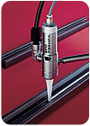
Today, more than three-quarters of industrial dispensing is done using some type of pneumatic valve employing the principle of time-pressure dispensing. At its most basic, this means the material being dispensed is presented under pressure to a valve where an air pulse-regulated by a programmable, digital controller-activates a piston connected to a stopper, which allows the material to flow onto the work piece via a detachable, disposable needle tip.In most cases, a spring returns the piston or stopper to the “closed” position at the end of the pulse. However, a second, controlled pulse can also be used to close the valve, to ensure that it snaps shut. According to Jim Bongiorno, plant manager at dispensing systems manufacturer EMC² Inc. (Sterling Heights, MI), this helps ensure crisp performance even when dispensing thicker materials. Among other things, air shutoff means the system controller isn’t forced to work against the force of the spring when opening the valve.
Michael DeFillipi, dispense technology manager at Ingersoll-Rand Productivity Solutions (Rochester Hills, MI), adds that some of his company’s air-on, air-off valves also incorporate a spring to ensure they remain shut when not in use.
In many ways, the simplest option is a pinch-tube valve. In this configuration, a disposable tube travels through the body of the valve, where a spring-loaded piston closes it off mechanically. In an automatic or semiautomatic setting, pulsed air forces the piston away from the tube, permitting the flow of material. In a manual setting, the operator does the same thing using finger pressure. In either case, a threaded bolt sets the stroke limit.
Because the tube is disposable and eliminates any contact between the valve body and the material being dispensed, pinch-tube valves are often used when dispensing highly corrosive materials or fast-acting materials that might ruin the valve by curing inside the valve body. Pinch-tube valves are also relatively inexpensive, both to purchase and maintain.
On the downside, pinch tubes can only be used with lower-viscosity materials and materials that are being dispensed under low pressure. In fact, they are often used in gravity-fed systems.
Another valve type often used with corrosive or reactive materials is the diaphragm valve. In this configuration, a spring once again maintains a piston in a closed position. However, this time the system isn’t simply pinching off a disposable tube. Instead, it is holding a diaphragm “plug” against an orifice through which the material must pass to exit the valve body. In operation, a pulse of air forces the piston back, which in turns allows the material to flow. When the pulse stops, the spring returns the piston and diaphragm to the closed position, stopping the flow.
As is the case with pinch tubes, diaphragm valves are highly resistant to the effects of sensitive or corrosive fluids, because the diaphragm separates the valve’s actuating parts from the material being dispensed. For example, Tony Turner, sales manager at Ashby Cross Co., says diaphragm valves are often the system of choice when dispensing cyanoacrylates, because this type of adhesive can’t come in contact with the metal in the valve’s moving part.
Diaphragm valves are also lightweight, easy to maintain and remarkably durable. John Olevich, vice president of engineering at Glenmarc Industries Inc. (Chicago), notes that, depending on the materials used, diaphragm valves can be very tough when coupled with stainless steel construction, even when dispensing abrasive substances. “[We have] a special flexible diaphragm made from proprietary material developed in-house that can dispense abrasive materials for millions of cycles,” he says.
On the down side, the nature of the diaphragm is such that, while these types of valves can be used with both low- and medium-viscosity materials, they can’t handle thick greases, pastes or other materials being dispensed under high pressure. However, for these types of operations, assemblers have the option of the ubiquitous needle valve, a piece of equipment found in everything from the electronics to the automotive industries.
Using this approach, a piston-driven needle stops the flow of material when it is in the closed position, resting in a seal, or seat. When an air pulse drives the piston back, it also lifts the needle, allowing material to pass on through the disposable tip to the workpiece. A threaded, adjustable stop regulates the travel distance for the piston.
Although, the actual needle is in contact with the material being dispensed, needle valves employ various types of seals, packing and packing nuts to separate the material in the fluid chamber from piston and air cylinders. Wetted parts are available in either hard-coated aluminum or stainless steel, allowing them to stand up to harsh use. Seals and packing materials can be Teflon, an ultra-high molecular weight plastic or some other material, again depending on the material being dispensed. Sealant Equipment’s Tip-Seal line, for example, includes a carbide ball at the tip of the needle and a hardened seat, both to ensure a good seal and increase the life of the valve.
As an added benefit, because the needle shutoff point can be placed at the very end of the valve where it mates with the dispense tip, there is little, if any, dead fluid volume in the valve. This “tip-seal” configuration helps eliminate the problem of dripping between dispense cycles, says Doug Brady, worldwide product marketing manager for sealant and adhesive equipment at Graco Ohio Inc. (Minneapolis).
Although the use of the word “needle” might make these types of valves seem diminutive in nature, EMC² Inc.’s Bongiorno says they are well suited to high-volume applications as well. According to Bongiorno, needle valves can also be effective when dispensing gels that are sensitive to pressure and shear stress, because they require the material to take a minimum of sharp bends.
Brady adds that his company sells a lot of needle valves because of their long life and “robustness.”
On the down side, because of the small size of the needle orifice in low-volume applications, dispensing materials with fillers can be a problem, because the fillers can create clogs. However, in these instances, engineers have the option of going with a ball-and-seat type valve, which is similar in action to a needle valve, except the piston shaft has a ball at the end to seal off material flow. According to Sealant Equipment’s Ruhlmann, this type of valve works especially well with low- to medium viscosity materials.
Another possible solution for dispensing thicker materials is a poppet- or piston-type valve. In these cases, it is once again an air-actuated piston that opens and closes the dispensing channel. However, in contrast to a needle or diaphragm system, the piston moves forward, or down, to initiate material flow, lifting a sealing head off of an angled seat, before being pushed back into a closed position.
In addition to providing a large, clog resistant orifice, this kind of dispensing mechanism provides the added benefit of a “suck back,” or “snuff back,” that draws a little bit of the material back into the valve at the end of each dispense cycle. Basically, as the spring or air drives the piston into the closed position, the backwards movement of the sealing head creates a small vacuum in the valve tip. This approach can be especially effective for preventing drips when using medium to thick fluids like silicones and greases.
For even thicker materials, engineers have the option of going with a spool valve, in which a cylindrical stopper at the end of a spool is sealed using a gland or O-ring, and then actuated by a pneumatic cylinder. Like a poppet or piston valve, spool valves provide suck-back performance to ensure that drips aren’t a problem. However, because of their robust construction and spool configuration-which utilizes the force of the pressurized dispensing material to help close the valve at the end of each dispense cycle-spool valves are the valve of choice in high-viscosity applications.
Extra Precision
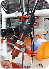
Unfortunately, all of these valves possess a kind of an Achilles heal in the sense that they are vulnerable to fluctuations in temperature, which in turn affects the material’s viscosity. They also lack the repeatability of a purely mechanical system in those applications requiring extreme precision.To combat these problems, valve manufacturers have developed air-actuated positive displacement valves, systems in which the material is allowed to fill an adjustable chamber within the body of the valve, which is then forcibly emptied during actual dispensing. Because the chamber determines the amount of material dispensed, regardless of pressure or viscosity, assemblers can be assured of dispensing the exact same amount of material every time.
It’s important to note, however, that even with these kinds of valves, assemblers can’t forget about temperature completely. Specifically, Ingersoll-Rand’s DeFillipi cautions that while shot size remains constant, viscosity will still change, which can affect cycle times as flow rates go down. For this reason, he says his company has equipped a number of valves with water conditioners to maintain a steady temperature.
Another way to ensure accuracy and repeatability in terms of shot size is to go with a servo-driven auger valve, a favorite of the electronics industry, where it is used to dispense precise amounts of solder paste. In these systems, the material enters the valve through one port under pressure and is then forced out through the dispensing orifice by a motor-driven Archimedes screw.
One of the keys to making the system work is creating just the right material pressure, so that the system maintains a prime, but material isn’t forced past the auger. The pressure, however, does not dictate the amount of material dispensed, as is the case with a pneumatic system. That’s the job of the mechanical screw.
If there’s a down side to this approach to dispensing, it’s that the auger screw can cause problems as a result of the forces involved as it pushes the material through the dispensing chamber. For example, in some cases, a filler metal can become separated from the rest of the solder paste. Then there is the problem of viscosity. Specifically, an auger system can’t be used with watery liquids.
Yet another approach is to use a positive-displacement syringe, in which a motor-driven piston, or plunger, forces the material out through a disposable barrel, thereby regulating the amount dispensed-kind of like a small, high-tech calk gun. Technically, the system is not a valve, but it performs much the same function. Because a motor is directly controlling piston position, the system is immune to the influence of environmental factors like temperature and humidity.
Positive-displacement syringes are also well suited to dispensing abrasive filled materials, like the thermally conductive adhesives that are increasingly used by electronics companies.
According to Tom Blanchard, vice president of sales at Fishman Corp. (Hopkinton, MA), these kinds of materials can quickly wear out the screw in an auger system or the precision components that make up an air-actuated positive displacement valve. “The stuff is like liquid sandpaper,” Blanchard says. However, because in a positive-displacement syringe the disposable barrel and plunger alone contact the material, it is immune to this kind of wear.
Finally, there are jet valves, a type of valve that is often used for dispensing everything from UV adhesives to epoxies, conformal coatings and underfill in the surface-mount electronics industry. With these systems, a fast-acting pneumatic piston with a ball-tip forces out the pressurized material in discrete droplets through a narrow hole at the jet nozzle tip. New advances in jetting technology use high-speed coils that, when energized, create a magnetic field pulling the piston-needle assembly off the nozzle seat. Cycle rates in excess of 200 times per second can be achieved.
Advantages include the fact that assemblers can precisely create very small dots and lines at a very high rate. Because the valve is “shooting” the material from a short distance above the substrate, there is less chance of equipment damage resulting from the valve or needle tip actually hitting the assembly.

