Robotics
Machine Vision Aids Robotic Assembly
Vision-guided robotics can help manufacturers improve accuracy, increase flexibility and decrease fixturing costs in automated assembly systems.
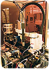
The integrator had been hired by contract manufacturer Nypro Corp. (Clinton, MA) to design an automated assembly system that could place tape-fed components for a cell phone with an accuracy of ±0.2 millimeter. Trouble was, the location of the components on the tape itself varied by ±0.3 millimeter. To make matters worse, the components, which included a gasket and a piece of cloth, were narrow and flexible. A conventional pick-and-place device was out of the question.
A vision-guided Cobra 600 SCARA robot from Adept Technology Inc. (Livermore, CA) solved the problem. Two cameras direct the robot. One camera is mounted directly over the feeders and tells the robot exactly where to pick up the parts. The second camera is positioned over the pallet, where the display window and front cover of the phone are fixtured. This camera tells the robot precisely where to place the parts. Lanco engineers designed a special gripper to maintain dimensional stability of the parts during assembly.
With the vision-guided robot, the system places parts with an accuracy better than ±0.2 millimeter, while achieving a cycle time of 3.4 seconds or less per part.
Such success may seem dramatic, but in fact, it’s not at all unusual. Advances in vision-guided robotics are helping a growing number of manufacturers improve accuracy, increase flexibility and decrease fixturing costs in automated assembly systems.
Even in the most precise assembly systems, the size and position of parts will vary slightly. In some cases, such variation is inconsequential. In others, as in the cell phone example, it’s critical. Vision guidance leverages the chief advantage of robots-programmable motion-to overcome this challenge. With vision, the robot can use fiducials or geometric features to precisely locate parts or assembly locations.
Vision guidance lowers fixturing costs by enabling engineers to use simpler, less expensive methods to present parts for pickup. Instead of custom-made, high-precision fixtures, parts can be loosely positioned in pocket tape, a bin or a flat surface, such as a conveyor.
“Precision fixtures hold parts so the robot knows exactly where to pick them up,” says Ed Roney, development manager for intelligent robot vision systems at FANUC Robotics America Inc. (Rochester Hills, MI). “But, those fixtures cost money, and they take time to make. If you use vision to locate the part, you save the cost of that tooling.”
Looking for quick answers on assembly and manufacturing topics? Try Ask ASM, our new smart AI search tool. Ask ASM
Similarly, vision guidance increases flexibility. Instead of swapping fixtures to run a new part, assemblers simply reprogram the robot and vision system. Moreover, vision-guided robots can distinguish between parts that differ by size, shape or even color. This allows a robot to handle more than one part or assembly at the same time.
Of course, a vision system can do more than just locate parts, adds David Arceneaux, business development and marketing manager for Stäubli Corp. (Duncan, SC). At the same time that the vision system tells a robot where to retrieve a part, it can measure the part, inspect it, or read an identification code from its surface.
How It Works
Vision guidance can be used with any robot: Cartesian, SCARA, six-axis or delta. Vision guidance can be integrated into a robotic application from the beginning, or it can be added to an existing setup. Some suppliers offer robots with integrated vision guidance systems, but engineers can also use vision systems from outside suppliers.
“The advantage of an integrated vision system is that the vision programming software is part and parcel of the robot programming software,” says John C. Clark, national sales manager at EPSON Robots (Carson, CA). This ensures that nothing gets lost in translation when information passes from the vision system to the robot.
Communication between the vision system and the robot can be an issue in guidance applications, but suppliers of the two technologies have been working closely to resolve it. For example, vision supplier Cognex Corp. (Natick, MA) has inserted pretested blocks of code, called snippets, into its software to facilitate communication with robots from several suppliers. “If you’re communicating with a DENSO robot, all you need to do is specify that in the software, and the programming string will be preformatted to communicate with a DENSO robot,” says Brian Boatner, product marketing manager for InSight vision sensors at Cognex.
In addition, sample code for guiding robots from DENSO Robotics (Long Beach, CA), ABB Inc. (Auburn Hills, MI), FANUC and other companies can be downloaded from Cognex’s Web site.
To implement vision guidance, engineers need the same components as any machine vision application: a camera, a lens, lighting and an image processing system. The latter can be a PC equipped with a frame grabber, or, the camera and image processor can be bundled into one convenient package, the so-called smart camera.
The camera can be mounted to the robot’s arm or to a stationary support in the workcell. In most cases, the best location for the camera is a fixed position above the work area. This keeps the camera out of harm’s way, and it minimizes the impact of vision guidance on overall cycle time. “When the camera is in a fixed position, it can be looking for parts while the robot is doing something else,” says Roney. “If the camera is on the robot, the robot has to position the camera above the work area and wait for the camera to acquire a part. The camera cannot take a picture in just any location.”
On the other hand, if the application requires extreme accuracy, mounting the camera on the arm can be advantageous, because the robot can position the camera very close to the parts. In addition, mounting the camera on the robot may obviate the need for more than one camera if the robot needs guidance at multiple locations. Cameras as small as D cell batteries are now available for mounting on a robot arm without compromising its mobility or payload capacity.
Access is another reason to mount the camera on the arm. “In some applications, such as semiconductor manufacturing, the robot has to go inside a machine to retrieve the parts. In those cases, it’s not feasible to locate the camera inside the processing chamber,” says Arceneaux.
As with any vision application, lighting is critical. Diffuse on-axis lighting is necessary to locate parts with reflective surfaces. Off-axis lighting, which creates shadows, is required to find stacked parts or parts with uneven surfaces. Ambient lighting is rarely sufficient for robot guidance.
Once the camera and lighting are set up, the next step is to calibrate the system. Calibration enables the vision system to output positional data in coordinates that the robot understands.
The simplest way to calibrate the system is to have the camera measure a reference object. “If you put a 2-inch gauge block under the camera, and the camera sees the block is 200 pixels wide, you know that each pixel represents 0.01 inch,” explains Boatner.
That method is quick and effective, but it doesn’t account for image distortion related to the lens or the camera’s perspective. For example, certain lenses may cause features at the outer edges of the image to appear pulled in. Or, if the camera is mounted at an angle to the object, instead of perpendicular to it, the front of the object will appear larger than the rear.
To overcome those challenges, engineers can place a grid of uniformly spaced lines or dots below the camera. By analyzing an image of the grid, the system knows that X number of camera pixels corresponds with Y number of millimeters. In addition, “when you tell the vision system what the line spacing should be, the software automatically unwarps the image, correcting for any distortion from the lens or perspective,” says Boatner.
This method gives assemblers more flexibility in where to locate the camera and what type of lens can be used.
Regardless of the calibration method, engineers are well-advised to perform the process carefully and precisely. Calibration is particularly critical if the parts tend to rotate, or if the camera’s field of view is small and the robot moves a large distance away to perform an operation.
“Calibration is very important,” says Roney. “The smallest errors will magnify...so spend the time up front and really lock down the calibration.”
Once the system has been calibrated, engineers must teach it to identify the parts. Good vision software should be able to find the parts despite minor problems with contrast, part orientation or overlapping parts. Engineers can anticipate problems by testing the system under deliberately adverse conditions. “Change how the part is lit. Cover it up partially. Rotate it around. Move it up and down in the field of view. Move it out of focus,” advises Boatner. “You want to see how repeatable the pattern-matching program is, because that’s the key to a successful application.”
Although vision guidance allows engineers to present parts to a robot without the need for precision fixtures, there are practical limits on just how loosely the parts can be positioned. If the parts lay flat, there’s almost no limitation on how loosely they can be positioned within the camera’s field of view. Nevertheless, many assemblers will run the parts beneath a brush or rail to keep them from overlapping, says Boatner.
Seeing in 3D
A two-dimensional image is usually sufficient for most vision guidance applications. However, some applications are better served by three-dimensional imaging. For example, 3D imaging is ideal for bin-picking applications and for locating parts stacked on top of each other.
Three-dimensional vision guidance is required when there are no grip-relevant features on the part, when the part’s normal resting position is not reproducible, or when the system has difficulty obtaining a high-contrast 2D image, says James Anderson, product manager for machine vision at SICK Inc. (Minneapolis).
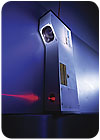
Three-dimensional images can be obtained in several ways. For example, SICK’s IVC-3D smart camera uses laser light and triangulation. The laser scans the parts, creating individual linear profiles that are combined to create a 3D image. The laser can scan up to 5,000 profiles per second. Because the camera relies on triangulation, it can detect geometrical features regardless of fluctuations in contrast. The IVC-3D is available in two models. One has a measurement area of 150 by 50 millimeters and a resolution of 0.1 millimeter. The other has a measurement area of 600 by 200 millimeters and a resolution of 0.5 millimeter.
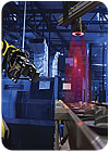
In the TrueView 3D vision guidance system, which was developed by Braintech (North Vancouver, Canada) and licensed to ABB, a single camera and variable lighting are mounted on the robot’s end-effector. The robot automatically positions the camera and adjusts the lighting to obtain an optimal 2D image, from which the image processing software extracts 3D information.
The software’s underlying principle is projective distortion, explains James M. Dara, vice president of sales and general manager of operations at Braintech. All optical systems use lenses to form images. All lenses cause varying degrees of distortion. As a result, features or landmarks change in appearance and relative distance and position when either the object or the lens moves. If the actual size and shape of the object without distortion is known, then comparisons to the apparent image can give information on position, distance and orientation.
Automakers have been using the system to handle parts such as cylinder heads, engine blocks, intake manifolds, fuel tanks, transmission cases, axle knuckles and truck frames.
The Future of Vision Guidance
As machine vision becomes more tightly integrated with robot control systems, engineers will be able to program robots to behave much more like human assemblers. When you assemble something manually, your hands adjust automatically to any movement of the parts. You hardly think about it. Imagine you’re reaching for an object swaying in the wind. Guided by a continuous stream of data from your eyes, your hand would simply follow the course of the object and grasp it. You wouldn’t take one look, close your eyes, and grab for it.
Yet, that’s exactly what a robot does in a vision-guidance application. “Right now, the vision system takes a snapshot of a single point in time,” says Roney. “It figures out where the part is at, and tells the robot where to go. What we would like to do is take pictures constantly, see how the position of the parts changes over time, and adjust the motion of the robot accordingly. That’s true guidance.”
The concept, called visual servoing, is just around the corner. “The limitation on visual servoing has always been the speed at which we can get data into the robot,” Roney explains. “Communication over a serial port or an Ethernet port is fast, but not fast enough.”
Looking for a reprint of this article?
From high-res PDFs to custom plaques, order your copy today!


