Imprinting Data Matrix Codes
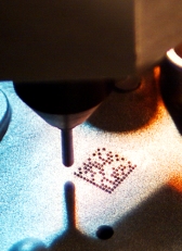
An increasing number of industries is using direct part marking to enhance process control and help resolve warranty issues. Photo courtesy Columbia Marking Tools Inc.
Although they look like tiny crossword puzzles, Data Matrix symbols are, in fact, comprised of a number of distinct regions, or zones. Running along two sides of each Data Matrix symbol are a pair of solid lines or a series of dots forming what looks like an "L." This is called the finder pattern and allows a reading system to precisely locate the code within its field of view.
Running along the other two sides of the square are lines of alternating squares or dots, depending on the method used to place the symbol. These represent the clocking pattern for the code, and serve to define the contrast between the light and dark portions of the symbol.
Contained within these two regions is the actual data region, made of up of lines of light and dark dots or squares-called elements, modules or cells-each representing one bit of binary data. Depending on its size, a Data Matrix symbol can store anywhere from six to more than 3,000 digits in a single code. Data Matrix symbols can be made as small as 2 millimeters across, but typically measure 10 millimeters or more to enhance data capacity and readability.
No matter what the dimensions, it is essential that the code have perfect right angles, that the contrast between the elements is consistent and that the elements are uniformly sized. Often, a symbol can be read even if it is scratched during assembly or while in use. But, if the symbol is afflicted by something more basic, say, uneven cell size or poor mark quality, it may be rejected. In addition, every Data Matrix symbol must be surrounded by a "quiet zone" approximately the width of a single symbol element to ensure there are no bumps, shadows or other features that will interfere with a machine vision system.
When choosing marking technologies, engineers have a number of options, depending on the type of component being marked. For example, when marking glass or creating clean, high-resolution marks on metal or plastic, many engineers select the laser-etch approach. This marking method is more expensive, but is extremely reliable and requires neither consumables nor the periodic replacement of worn parts.
At the other end of the cost spectrum are ink-jet printers. Unlike laser markers, ink jets create round dot-like cells, and require the use of a consumable. Inked symbols are also not considered to be "permanent" in many industries.
Between these two extremes are dot-peen markers, in which a pneumatic or electromagnetic driver is used to create the code pattern with the help of a hardened-carbide or diamond-tipped stylus. This approach can be used on a variety of surfaces, including steel, plastics and glass, and requires no consumables, although the styli need to be periodically replaced.
Finally, there is electro-chemical etching, which requires the use of a low-voltage current and stencil. In contrast to the other three technologies, this technique does not lend itself to high-volume production. However, it creates precise marks and does not weaken or distort the metal substrate, making it a good choice when marking fragile and thin-walled parts. For this reason, it is sometimes used in the semiconductor industry.
When deciding where to place a Data Matrix code on a particular part or assembly, engineers need to ensure that the code will be readily accessible to a machine vision system. It is also important that the surface be as smooth and flat as possible to facilitate reliable reading. For example, a cast surface can cause problems if the texture makes it hard for a camera system to differentiate the Data Matrix dots. Similarly, while it is possible to have some curvature in the Data Matrix symbol, too much will lead to readability problems.
No matter what the location or technology used, an increasing number of engineers are employing verification systems as an integral part of their part-marking program to ensure the highest level of readability. Similarly, experienced engineers make sure to think about an application’s particular part-marking needs early in the design process, as opposed to having to find a place for a Data Matrix code at the last minute. Doing so not only makes implementing a marking system much easier, but less expensive as well.
Looking for a reprint of this article?
From high-res PDFs to custom plaques, order your copy today!


