Assembly for Dummies
Surface preparation ensures strong adhesive bonds in load cells for crash test dummies.
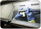
The microablasive blaster is used inside an enclosed workstation that collects the spent abrasive and protects the operator from inhaling the dust.
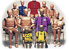
First Technology Safety Systems (FTSS) has been supplying automotive and aerospace manufacturers with crash test dummies for more than 50 years. These dummies have evolved from largely wooden products in the 1950s to highly sensitive assemblies of steel, aluminum, vinyl and rubber. Crash test dummies now come in all “ages” and body configurations-men and women, infants and adults, fat people and skinny ones.
FTSS handles every aspect of manufacturing the dummies, including design, molding, machining, assembly, calibration and testing. The goal is to make the dummies as close to human as possible.
For example, for the dummy for frontal crash tests, the skull and skull cap are one-piece cast aluminum parts with removable vinyl skins. The neck is a segmented rubber and aluminum construction with a center cable.
Six high-strength spring steel ribs with a polymer-based damping material are attached to a ballasted spine box to simulate the human thorax. Accelerometers are mounted on the sternum and in parallel locations on the spine. Low-friction guides restrain the vertical motion of the ribs, and bump stops prevent overcompression of the rib cage. A potentiometer measures deflection between the spine and the sternum.
The lumbar spine is a straight cylindrical column of butyl rubber. This keeps the dummy in an erect posture while seated. The pelvis consists of vinyl skin and urethane foam molded over an aluminum casting. The iliac wings of the pelvis can be fitted with six load bolts to measure the load points of the seat belt. Femurs, knees, shin bones, ankles and feet round out the construction.
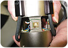
Small, delicate gauges and tiny cables must be bonded to the load cell. To ensure a good bond, the surface of the load cell is roughened to improve adhesion.
Building Load Cells
Crash test dummies are equipped with multiple load cells that provide detailed measurements of impact forces during experimental crashes. Each dummy needs load cells in a range of sizes and configurations. Some load cells are two-axis units; others are six-axis units. The number, size and type of load cells in a dummy vary depending on their location in the skeletal structure, the severity of the test, and the type of data that engineers want to obtain. For example, a six-axis load cell is positioned between the lumbar spine and the pelvis.FTSS manufactures load cells in-house. Depending on orders, the facility may assemble several styles and quantities of load cells daily. The requirements of automotive and aerospace manufacturers change constantly, and FTSS has to change with them. For example, the company has recently seen an increase in requests from automakers for side-impact dummies.
In one part of the load cell assembly process, small, delicate gauges and tiny cables are bonded to the load cell. This must be done exactly to create a good electrical circuit.
To ensure bond integrity, the surface of the load cell is roughened to improve adhesion. To achieve this texture, assemblers use a technique called abrasive-blasting. Each load cell is masked to cover areas that do not need abrasion, and then the exposed areas are lightly sandblasted. After abrasion, the masking is removed, the cell is cleaned, and the wires are bonded with an adhesive. After the adhesive is cured in an oven, the gauges are installed in the load cell. Next, the load cell is tested and calibrated to ensure that it’s reading correctly. At that point, a calibration sheet is issued, and the load cell goes to the dummy assembly area.
The load cells are mechanically attached to the dummy. Once the dummy is complete, it goes through a set of tests, including impact and drop tests, to ensure that it’s working correctly. During these tests, cables are attached to the load cells, and data is automatically transferred to a computer. FTSS engineers have developed custom software to handle the testing process. This data becomes part of a final certification sheet that stays with the dummy when it’s shipped to the customer.
That information is important, because some load cells will need to be replaced during a dummy’s lifetime. Using the test data, FTSS engineers can recalibrate the new load cells to match the originals, so test results with the repaired dummy are consistent with previous tests. The only time a full dummy needs replacement is when the outer skin begins to degrade.
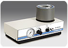
The MB1000 MicroBlaster provides a consistent stream of abrasive media with rapid starts and stops.
The Challenge
While abrasive-blasting is effective, the process must be tightly controlled to get consistent results. Abrasion can’t be too light or it won’t improve surface roughness enough, resulting in debonding of the gauges. At the same time, surface roughening can’t be too harsh or uneven, or it will destroy the surface of the load cell. When done correctly, abrasive-blasting provides moderate surface texturing spread evenly across the surface.Not long ago, the company’s sandblasting equipment was becoming unstable, and the effectiveness of the process was diminishing. Blasting pressure was hard to regulate. In fact, pressure was fluctuating so much that the blasting process often had to be repeated.
Moisture was also becoming a problem. Moisture was continually getting into the lines of the machine. Abrasive blasting requires clean, dry air mixed with a pure, uniform, micron-sized abrasive media. This mix of air and media is projected at a regulated pressure through a nozzle that is pinpointed at the area to be textured. For the load cells, the abrasive media is aluminum oxide, which is sensitive to moisture. With the slightest amount of moisture, the material clumps together and clogs the feed lines and nozzle.
To solve these issues and get back on track, FTSS replaced its current equipment with the MB1000 MicroBlaster from Comco Inc. (Burbank, CA).
The machine’s modulator and pinch-valve ensure a consistent stream of abrasive media with rapid starts and stops. Nozzles come in a range of shapes and sizes to suit various applications. The unit’s powder tank can hold 2 pounds of material and is easy to refill.
The microablasive blaster is used inside an enclosed workstation that collects the spent abrasive and protects the operator from inhaling the dust. A desiccant-bead or membrane-style air dryer prevents moisture from getting into the air line.
The operator holds a masked load cell inside the workstation, points the nozzle at the area to be textured, and activates the abrasive stream with a foot pedal. Air flows through the front of the chamber, around the workpiece and is pulled out of the back of the chamber by a dust collection unit. This keeps the work area clean and maximizes visibility during blasting. The workstation is also equipped with special features that minimize electrostatic discharge.
Today, production at FTSS is back on schedule. The load cells are evenly abraded using particles of aluminum oxide 27 microns in diameter. Blasting pressure is a steady 80 psi. Now, every load cell is abraded perfectly the first time around, and downtime from clogs is nonexistent. It doesn’t take a dummy to figure out that quality and profitability will result.
Looking for a reprint of this article?
From high-res PDFs to custom plaques, order your copy today!


.webp?height=200&t=1749742809&width=200 "Ford Begins Capri and Explorer Battery Pack Assembly in Cologne.jpg")
